The article shows an earthquake sensor circuit idea which incorporates an innovative way of detecting the minutest of shocks caused by a possible earthquake tremor. The circuit is so sensitive that it is able to detect tremor of 4 on the Richter scale, yet remains unaffected to loud sounds or irrelevant bangs or noises.
Introduction
I have seen a number of different circuits of seismic sensors on the net, however most of these have utilized a piezo transducer as the sensor element, God knows how a piezo would detect earthquake tremors.
It simply appears absurd because a piezo transducer would be solely able to sense high frequency vibrations and never a swaying action.
An earthquake will never generate a shrill noise rather it produces a gentle swaying pattern, when it hits.
Therefore using a piezo element is a flop idea, according to me.
Of course a piezo would detect tremors only if it were used in the form of a load-cell, by integrating some kind of load, assembled for implementing an oscillating action during tremors.
In the present earthquake sensor circuit, I have used water as the detecting agent.
After some experimentation I found that water is an excellent sensor of vibrations as well as a swaying kind of motions.
You can test waters behavior by keeping a bowl of water on the table and giving a gentle knock on the table.
Even the slightest of legit vibration is enough to create a nice ripples on the surface of the water.
I could have used an LED/LDR arrangement for detecting these ripples, however since we are not interested in sensing vibrations rather only swaying actions, I made a little out of the way approach.
Through a few of my previous posts I have already discussed water level sensor circuits where the water's conducting property is well exploited for the purpose.
The same property has been harnessed for getting the intended results.
How the Earthquake Sensor is Designed to Operate
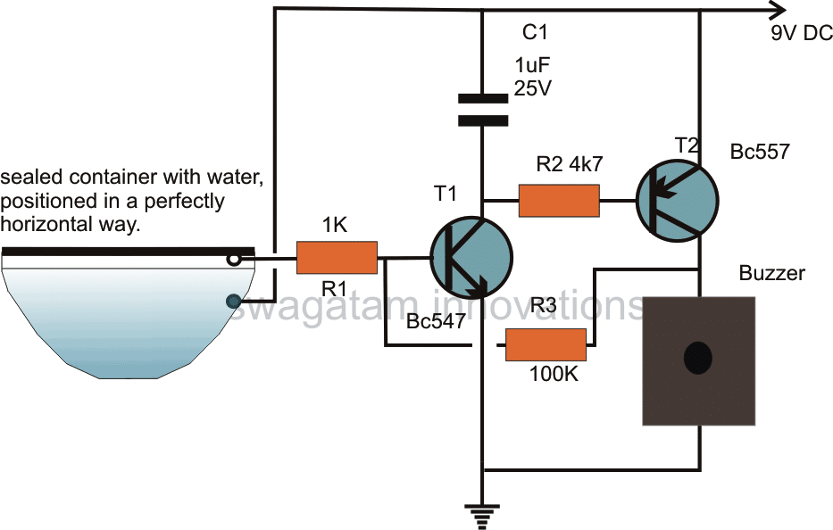
Looking at the circuit diagram we see that the configuration in fact has nothing serious.
The electronic part consists of a couple of transistors rigged into a latch circuit.
The input to this circuit is achieved from a small half round container filled with water.
The positive supply from the circuit is dipped inside the water while the hot end of the input is placed in such a way that it stands just a mm above the water.
During a possible earthquake (God Forbid) the water responds to the tremor and starts generating a swaying movement.
The moment the water moves, its level gets disturbed and connects the hot end of the circuit with the positive terminal, dipped inside the water..
The positive of the supply immersed in the water instantly makes contact with the HOT end of the circuit via the water, the circuit gets triggered and immediately latches.
The connected buzzer sounds, sending an alarm signal.
The container can be made by cutting a small children plastic ball into half.
After doing the required settings inside this half cut ball, it may be filled with water as shown in the diagram and sealed.
The container then should be fixed somewhere such that the level off water inside the ball retains perfectly horizontal position without any deviations.


Questions & Answers
The water in troumbler dry immediately..any solution?
You can seal the container with a lid, so that the water does dry up or evaporate.
I have got an electrolytic capacitor…. Which end of it should be connected to the transistor?
positive lead will connect with the positive line, negative to the transistor
Sir is the capacitor used in the circuit a ceramic capacitor or any other type?
Deep, it can be any type, polar or non-polar, ceramic whatever you can get.
yes that's right!
Hi, iam a mechanical engineer iam working on a hydroponic farm project now and I need some help on a timer circuit can you please help me out I need yor email id so that i can share my project setup with
Hi, my email is in the contact page, or you can also find it at the top portion of the sidebar.
sir can I ask what is the radius of the sound that the buzzer can make? at least what approximately 1 room or what? thank you
the buzzer will latch and sound continuously until the power is switched OFF and ON again
sir once the water touch the hot wire and the circuit was closed.. will the buzzer continuously alarm even the hot end don't touch the water anymore?
Gomnic, you can replace BC557 with a TIP127 transistor and use a high power car siren in place of the buzzer, that would upgrade the sound to a huge level.
the shown buzzer will be able to alert only around the area where it's installed
what shud be the specification of buzzer
it can be a 12V piezo buzzer….
hello sir i want to ask if is possible you can tell me where i can found the working principle of the circuit please answer me
Hello kwizera, it will not measure, it will only get triggered at approximately 4 Richter scale
as soon as there's a slight tremor detected, it will sound a alarm.
hello sir, i want to ask what did you mean Richter scale because i found that it is the measure of strength of an earthquake but earlier comment you told me that it cannot measure but it will detect then tell me how it can detect detect on 4Richter scale? thank you.
as soon as the building experiences a slightest bit of movement due to the tremor, this circuit will activate and sound the alarm.
then sir in which distance it can detect the tremor? and if it can detect it before someone who is close to the ckt hear it
hello Kwizera,
the circuit is designed to detect and sound an alarm, it will not measure the level of the earthquake…and it cannot detect tremors before it actually takes place
hello sir i want to ask if this circuit can measure the strong of an earthquake bcz you have said it in the introduction that is so sensitive to detect tremor on 4 Richter scale and i have seen that Richter scale is measure of strong of an earthquake and if it can detect tremor before people hear it plz tell me.
T1 and T2 are configured to switch ON and latch when the input is triggered via the water movement.
the 100k is the feedback link which initiates and sustains the latching effect
sir is any problem when i say that 100k will work as feedback
sorry sir i was thinking that my comment is no more needed but i will never delete it again but sir did you mean that T1 and T2 will work as suitch
why did you delete the earlier comment?
cap will prevent accidental switch ON latching of the circuit….but when actual earthquake ir detected the circuit will latch through the 100k resistor and T1/T2 combination
sir what's meaning of latches bcz you have said cap will prevent the latches and R100 latches the ckt plz tell me and T1andT2 will latch up what it mean
….sorry that was for R1/R2….T1 and T2 are connected such that they latch up when triggered.
for biasing the transistors so that they can turn ON
Hello Sir, I am beginner and question may be nonsense, sorry for that.
Is circuit positive in through the 1K resistor or capacitor. I made it but it just works connecting to positive in + to 1k resistor end in the water tank. Thank you.
Hello Peremeci, The positive is connected only to the capacitor C1 and the T2 emitter, 1K outer end is connected only with the water vessel, NOT with the positive.
hello Kwizera, the working principle is explained in the article itself.
hello, the circuit will sound an alarm as soon as the house begins trembling.
nothing has been invented in this world so far that has the capability of producing a prior warning indication.
Aw, That's Of Sweet Of You? Thank You, Mr. Kevin! God Will Bless Y
ou No What Matter What Happens He's Always There For You Whate
ver You Need Him Just Fear Him And Pray To Him And Confess!
PS God Will Never Let You Perish In A Storm or Disaster And Alw
ays Faithful And Good In Hard Times And Trouble Coming You
r Way In Life!
Yes, You Can Replace Your Bc557 With Other Transistor And You'll Figure It Out By Yourself And If Any Trouble You Can Always Reach
Me By Contacting Through Email? Thanks, Man You're The Best!
Well. Did You Try To Shake This Up With A Table And It Might Work
Unless You Have A Right Tool For Your Earthquake Project? Right,
Maneral? Good? Thanks For Your Nice Post!
I am confused about your other circuit "Cheap Semi Automatic, Tank Water Over Flow Controller Circuit". In that circuit has no positive supply at the collector of Darlington pair. Kindly clear it for me.
T1/T2 are kept for grounding the base of T3 when the water level reaches the top of the tank, here the base voltage of T3 becomes the positive for the Darlington.
I am using this circuit after some modification as water level cum pump controller circuit. But unable to upload modified circuit.
can i get this circuit sir…my email is susanlama12@gmail.com…plz email me the design
thanks, I got it, it's a very simple and useful design for controlling water over flow in tanks.
circuit is sent to hitman2008@live.in . power supply for motor is used when relay is inactive and when relay activated power supply of motor stopped. means when water touches touch point relay activated and power of motor is stopped.
you can send it to hitman2008@live.in