The article details about an automatic water flow controller timer circuit which switches a valve mechanism ON/OFF as per a set predetermined timing sequence. The idea was requested by Mr. John Clarke.
Technical Specifications
I've seen your site and designs and wondered if you could help with a controller I'm trying to design to control water flow on a shower.
What I'm trying to achieve is the following,
Using a water flow sensor, when water starts to flow a timer is triggered and starts a countdown of circa 2 minutes. After this time a control valve turns off the water supply and remains off for 8 minutes. After that time the control valve is re opened and the system resets to start again.
Ideally the two times would be adjustable.
Many thanks for any help you could give or if you can point me in the direction of where to go.
Kind regards
John
The Design
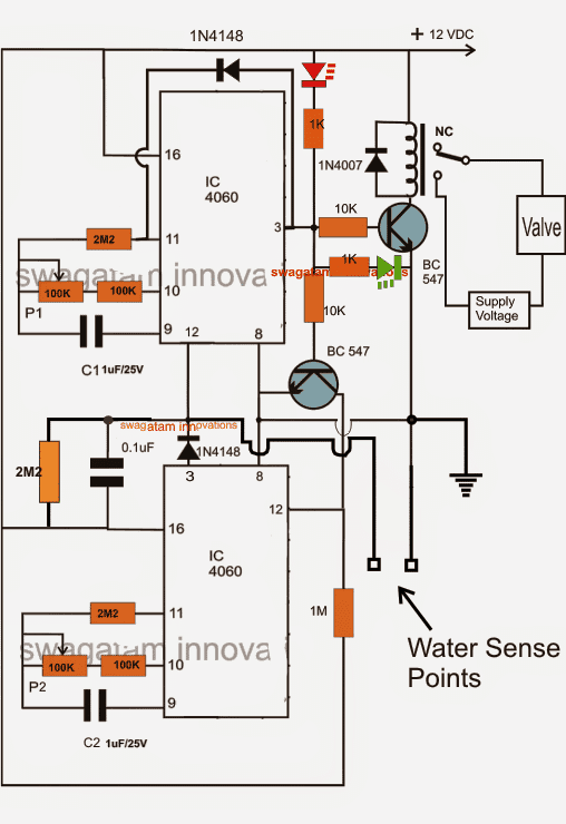
The proposed water flow controller circuit using a valve timer circuit can be implemented by using a simple two stage programmable timer design, as shown in the above diagram.
We have already discussed this programmable timer circuit in one of my previous posts. The same concept has been employed in this design too.
Referring to the diagram above we can see two identical timer stages using the ICs 4060 which are coupled with each other such that when the upper module finishes counting, the lower gets triggered and the sequence continues infinitely from the upper timer to the lower and back to the upper timer module.
The functioning of the system may be understood as I have explained below:
How it Works
When power is switched ON, the circuit stays disabled since pin12 of the upper IC has no access to a ground for initiating the counting process.
However the moment water is introduced across the shown "water sensing points" the pin12 of the upper IC experiences a ground potential through these sensing conductors and instantly initiates the counting process.
The initialization begins with a low at pin3 of the upper IC, the red LED now lights up indicating the start of the counting process by the system.
After about 2 minutes which may be set by appropriately adjusting P1, C1, the upper IC finishes its counting reverting its pin3 with a high logic, which instantly triggers the relay through the connected BC547 driver stage. The relay clicks energizing the water valve mechanism into action.
The green LED simultaneously lights up acknowledging the above activation of the relay and the valve.
The high from pin3 of the upper IC also makes sure that the IC latches itself and stops counting for the time being, this is implemented by the diode that's connected across pin3 and pin11 of the upper IC.
The above discussed high from the pin3 of the upper IC simultaneously triggers the lower BC547 into conduction which in turn grounds the pin12 of the lower IC, ensuring a triggering signal to the lower IC.
The lower IC now begins counting until 8 minutes have lapsed, this time period may be appropriately set by adjusting P2/C2 of the module. Once this set period elapses the pin3 of the lower IC goes high, "kicking" a triggering pulse to pin12 of the upper IC, which responds to this and instantly resets the upper IC into its original state so that it begins counting its stipulated 2 minute slot.
The above procedure switches OFF the relay and the valve mechanism providing a free path for the water to flow again, for until 2 minutes have passed and the cycle repeats, but only as long as the water sensing points remain subjected to a water content.


Comments
I found the above article intriguing about a water flow meter timer. This is exactly what I’ve been searching for to use on my shower. It seems you have nailed what I want. However, I am not electrically gifted and would love the opportunity to buy such a device either from you or if you know where I may purchase one that would be ace. Thank you.
I am glad you found this concept useful, however since we no longer manufacture electronic items it may be difficult for us to provide you an assembled product of this project.
Hello sir,
I want to make a circuit for water fountain.
It would work like, the switch is on it will work for30 min and will be off after 30 min and then switches off.
How would I make it kindly help me.
Hello, for 30 min ON and then OFF, you can use any one shot timer circuit, or a monostable circuit based on IC 4060 or IC 555 and use it for your requirement.
you can use the first circuit from this page
https://www.homemade-circuits.com/p/ic-555-calculator.html
connect a 10k across pin2 and positive, and a 1M across pin2 and ground…and also connect a 4.7uF capacitor parallel with the 1M.
then calculate the R/C values for the 30 minutes one shot operation.
pin3 could be configured with a relay
Dear Swagatam ,
I need a battery charger with working convert 226VDC to 12VDC at 20 to 25 AMP.Please help me design this type Battery charger i have 400 Aph Battery. and in your pervious blog i read the 220 volt DC to Ac Inverter does this inverter working with Solar panel of 226 VDC and 1KW solar power plant.
Dear Muhammad,
you can try the following design, this will perfectly suit your application need:
https://www.homemade-circuits.com/2014/06/smps-2-x-50v-350w-circuit-for-audio.html