In this post I have explained an enhanced multi-spark CDI circuit which is universally suited for all types of automobiles. The unit can be built at home and installed in a particular vehicle for achieving greater speed to fuel efficiency.
The Circuit Concept
The following diagram illustrates an enhanced version of a multi-spark CDI circuit. Fundamentally it can bifurcated into two discrete stages.
Both the stages incorporate the IC IR2155 MOSFET driver with built in 50% duty cycle oscillator.
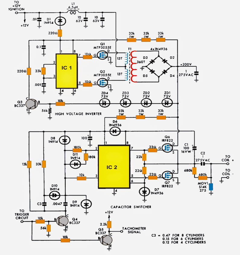
The upper stage consisting of Q1, Q2 are configured for generating 300V DC from the available 12V DC input battery supply.
The IC2 along with the connected mosfets Q6/Q7 form a push pull type pump circuit for alternately charging and discharging a high voltage capacitor across the connected ignition coil.
Circuit Operation
IC1 is wired up for oscillating at about 22kHz as per the selection of the 33k resistor and the 102 capacitor across pin2/3 and pin3/ground respectively.
This results in producing alternate switching of its output mosfetsQ1/Q2 connected across pins 5/7.
The above switching performs a push pull reaction over the connected transformer wherein the two halves of the winding are saturated alternately with the mosfet conduction, which results in pumping of the entire 12V DC across the two half winding of the transformer.
This action results in a stepped up induction across the secondary winding of the transformer giving rise to the required 300V AC switched at the 22kHz rate.
The mosfets have their own internal transient protection system built in in the form of 60V zener diodes which limit the internal spikes to 60V safeguarding them from the relevant dangers, also the external gate 10 ohm resistors ensures a relatively exponential charge and discharge of the mosfet internal capacitance thereby reducing noise and disturbance which could otherwise influence the vehicle electrical adversely.
A couple metalized capacitors rated at 10uF are installed in order to decouple DC from T1 so that Tr1 receives the 12V switching optimally across its winding.
The stepped up voltage at the output of TR1 is rectified by the 4 fast recovery type diodes configured as a bridge rectifier.
The ripples are further filtered by the metalized high voltage capacitor rated at 1uF/275V
Even with the all the above high efficiency and protected circuitry, the IC1 stage has no ability os controlling the output voltage in response to the rising and falling of the 12V DC input which normally wouldn't be stable due to the vehicle's speeds and alternator RPM variations.
To tackle this, an innovative transformer output voltage correction feature is Incorporated here using a voltage feedback circuitry involving ZD1---ZD4 along with Q3 and a few passive components.
The four 75V zeners start conducting as soon as the voltage begins drifting above the 300V mark, which in turn results in the conduction of Q3. This action from Q3 results in dragging pin1 voltage of IC1 from 12V to gradually 6V.
Using the Shut Down Option
Pin1 being the shut down pinout of the IC1 alerts the IC to trigger its internal under voltage cut-off feature resulting in an instantaneous shut down of its output pulses which in turn switches off the mosfets for that particular instant.
The mosfets being switched OFF means no output voltage and Q3 unable to conduct which again restores the circuit to its original functional mode, and the operations repeat and rotate keeping the output voltage quite stabilized at the specified 300V volt mark.
Another clever enhancement technique employed here is the use of three 33k resistors feedback loop from the output of TR1 to the IC1 supply pinout.
This loop ensures that the circuit stays functional even when the vehicle is not running at optimal speeds or the supply voltage dropping considerably below the required 12V level.
During such situations, the discussed 33kx3 feedback loop keeps the voltage level to IC1 well above 12V ensuring optimal response even under conditions with steep voltage falls.
The 300V from TR1 is also applied to IC2 which is specifically configured as a high side mosfet driver, because here its output is not connected with a center tap transformer rather a single coil which needs a full drive across its winding in forward reverse method during each alternate pulse from IC2.
Thanks to the IC IR2155 which has all the necessary features built in and effectively starts working as a high side driver with the help of just a few external passive parts C1, C6, D7.
Function of the Ferrite Transformer
The conduction of Q6/Q7 pumps the 300V volts from TR1 inside the connected ignition coil primary via the 1uF/275V capacitor.
The calculated configuration of various components across pin2 and pin3 of IC2 constitutes the intended multi sparks across the connected coil due to the interactions between these components. More precisely, the parts form a timer design with the help of the 180k resistor at pin2 along with the 0.0047uF capacitor across pin3 of IC2.
The 10k resistor and the 0.0047uF capacitor between pin3 restricts over current while it's being triggered by the MMV circuit.
The output from Q5 facilitates a low voltage output for integrating a tachometer in order to provide valid readings on the meter rather than connecting directly to the spark plug.
If in case the multi spark feature seems not so useful or for some reasons inappropriate then it can be successfully disabled by eliminating C3, D10, D11 and the couple of 180k resistors along with the 33k and the 13k resistors. Also by substituting the 33k resistor with a 180 k resistor and a short link in place of D10.
The above mods will force IC2 to generate just single 0.5ms pulses as soon as Q7 is triggered. The ignition coil now fires only in one direction while Q7 is ON and in once in the opposite direction when Q6 is ON.
The associated MOV neutralizes any possibility of high voltage transients in case the output of the ignition coil is left open.
The couple of 680k resistors across C2 provides a safe discharging path for C2 whenever the coil is disconnected from the circuit.
This safeguards the circuit and the user from nasty high voltage discharge from C2.
Circuit Diagram
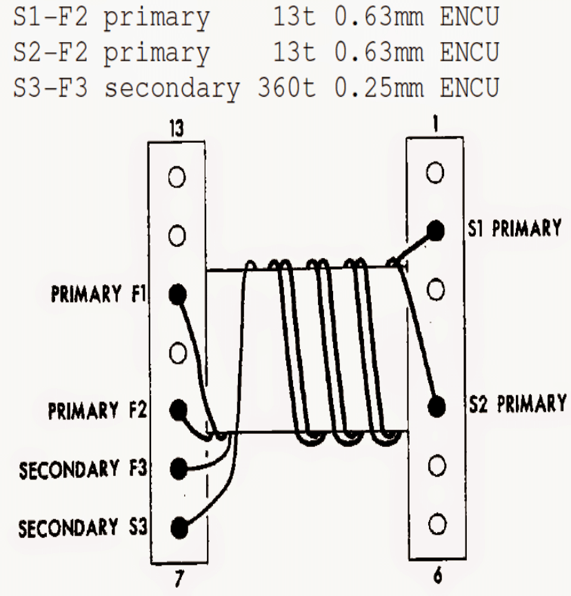
TR1 winding Details:
Start from pin7 (left hand side) using 0.25mm enameled super enameled copper wire as shown in the diagram and end at pin8(left hand side) with 360 turns.
This completes the secondary winding.
For the primary side wind in a bifilar manner meaning wind both the winding together, starting at pin2 and pin4 (right hand side) and ending after 13 turns at pin11 and pin9 respectively (left hand side) using 0.63mm wire.
The bobbin used is for suiting N27 Ferrite Core
L1 is 12 turns of 1mm wire on a Neosid Ringcore 17-732-22
Transformer Design


Comments
Hi, just wondering how to adapt this for a positive ground system as in old british cars?
Thanks.
Hi, if you can somehow isolate the whole circuit along with the spark plug from the car body then probably you can use the circuit as is without any changes.
Whats the part number of the ICs?
They are both IC IR2155
Thanks Swagatam..!! It seems like I won't be finishing this build…wanted to add the Murakami plasma spark to it to fire my water spark plug…thanks anyway for your replay and if possible could you suggest a different multi spark cdi circuit for this build…thanks..!
Hi Swagatam,
If Possible I would appriciate your help, as I built the John Clarke MSCDI but could only get 34v from it due to the availability of the transformer specs. Perhaps you'll be able to help with a more comenly available transformer and core design..?
Keep up the Good work and all of the best..!!
Regards,
Morné.
Hi Morne,
The transformer is the crucial element in this design and needs to be built exactly as given in the article, there's no other common variant of the trafo, you will have to build it exactly as per the given data
that's amazing DA, your efforts are commendable…please keep it up.
I've already similar schematic of MultipleSpark CDIS…. That original circuit was problematic…. Encountering repeatedly shorting of 2 Mosfer IRF822.
So, I made own design of MSCDIS still using same principle….
It was installed in my Mitsubishi Lancer 4 cylinder carburated engine since 2014 and still functioning properly..
It's now running 5 spark at 700rpm and the spark gradually reduce into 2 spark voltage reaching 5,000 rpm and remain 2 spark beyond 5,000 rpm….
High voltage Spark voltage was 30KV.
Only drawback was cheap spark and cheap high tension wire will not last up to 3 months… Need to use high quality High Tension Wire and spark plug.
I'm sorry to mention the brand of spark plug that I used….It's not my intention to endorse any product…. Sorry again…
OK, great!! thanks very much, appreciate your honest response…keep up the good work!!
This MSCDIS that I have built was personal use only….Some of my friend want me to build for them. but I decline…
I built this for just a personal challenge if I can make it work perfectly…
And I want to mention Mr. Swagatam. that your tutorial of SG3525 pwm ic really helps me to implement it in my circuit as dc to dc inverter for the MSCDIS…. Because IR2155 will not oscillate if car battery was 12V or below.
Thank you for your contribution to success of my MSCDIS.
thanks for the update, I hope this comment was not intended to endorse certain brands and company names…
can you change ic ir2155 with ne555
not possible
I need 3kva circuit for my project sir, can u help me
what circuit?
Please advise…on what to use at C3 for my 2 cylinder v-twin. Thank you again Sir.
Sincerely David.
You can try a 1uF…that can be expected to produce 220Hz, a compatible value for an iron core CDI coil.
Great Swagatam…Thank you kindly Sir.
David
you are welcome!!
Tried a post already and it dissappeared…sooo I'll be brief… can I use this cdi to run my vtwin suzuki 1400? Along with two of your adjustable cdi spark advance and retard circuit for motorcycles?
I have my old cdi dyna3000 already chipped clean if you want it for study…
Please advise.
Thank you.
Sincerely,
David Sellers
Hi David, If you are reasonably expert with electronic concepts and practical assembly work, then definitely you can try both the designs for getting high quality results.
However the advance/retard circuit which I have invented might require some tweaking and experimentation before it becomes practically implementable.
Hello Swagatam.
You can post a schematic of what you say.
My knowledge of electronics are very basic and on paper it look better.
Thank you very much.
Hello Ninja, it's very easy, take two diodes (1N4007), twist the leads together which are relevant to the banded side of the diode, connect this twist with the gate of the SCR and the two fee ends of the diodes can be now joined with the two pick up points.
Remember we are referring to the following article and not the above….
https://www.homemade-circuits.com/2011/12/how-to-make-capacitive-discharge.html
the twisted joint should be connected with the point in the circuit indicated as
"12V trigger from alternator"
you don't have to bother about the negatives because all the negatives are connected to the bike body by default, make sure the same is done with the CDI negatives also.
Hello again.
Sorry, I had forgotten to clarify this.
When I said 2 trigger is two pickup trigger.
Thanks. Regards.
OK no issues Ninja, in that case you can easily use a single circuit module as shown above and feed the two signals to the gate of the SCR through individual diodes, the negatives can be terminated as a common line and connected with the circuit negative.
for the diodes, and cathode should be joined and connected with the gate resistor, while the two free anode ends joined with the two positives from the pick up
Thanks for responding Swagatam.
I forgot to tell you, also I have two triggers, one for each coil.
And each trigger out a positive and a negative.
What do you think ?.
Thank you and congratulations again.
Hello.
First congratulations on your great work.
I can I use this cdi on a Kawasaki GPX 600R 1990.
This motorcycle has two coils, one coil for cylinders # 1 and 4, and another coil for cylinders # 2 and 3.
The highs are 11000 rpm.
Or any scheme that can serve me
I would appreciate your answer, because I broke the cdi, I have stop motorcycle and I want to repair.
Thanks in advance.
Regards.
Thanks Ninja,
Yes you can use the above circuit for your motorcycle, but I am not sure how to integrate the circuit with the two coils, may be two separate circuits would be required for feeding the two coils.
Hello Swagatam,
great job, thanks !
A question : how many spikes per trigger generate your circuit ?
Thanks
Zbig
Hello Zbig, it will depend on the values of the capacitor near D9 and/or the resistor near D11….these may be varied for getting different sets of multisparks
hello
can i use this cdi
to run 2 coil at the same time?
i have twin spark engine with 4 cylinder engine and 2 plug per cylinder
thank you
Adi
can i use this cdi
to run 2 coil at the same time?
i have twin spark engine with 4 cylinder engine and 2 plug per cylinder
thank you
Adi
yes you can do it.
Hi Swagatam
The main idea behind this circuit is get a burst of sparks instead of one spark against one triggering signal from the pick-up coil, i.e.
Normal CDIs => 1 tigger signal will result 1 spark
This CDI => 1 trigger will result more than one sparks
I was just wondering that it could be achieved using the simple CDI circuit
https://www.homemade-circuits.com/2011/12/how-to-make-capacitive-discharge.html
A 555-astable (at about 100kHz) can be used to convert each pulse (from the pick-up coil) into multi-sparks. The pulse from the pick-up coil could be fed at pin#4 of 555 and the output from the 555 can be fed at the trigger-input of the simple CDI circuit.
Frankly, I have already simulated it successfully. Just waiting for the completion of renovation work at my lab, to test physically.
Your valued comments, please 🙂
Hi Abu-Hafss,
Yes that's true, the fundamental frequency being low (in Hz), it won't force the eddy currents to violent levels, however since each of the pulses would be broken into many "pieces", it's hard to simulate how it won't affect the iron cored coil performance.
Hi Swagatam
100kHz is just my evaluation to have about 4 sparks in 4ms.
The circuit discussed in this article is also intended to yield multi-pulses against one pulse signal from the pick-up coil, and the same is pumped into the ignition coil via capacitor. If the ignition coil can respond to this circuit, why won't it respond to our proposed idea?
Hi Abu-Hafss,
Absolutely that's feasible, in fact if you see the fence charger circuit, since it's operated at 50Hz, the sparks also respond with a 50Hz output, however 100kHz could be a relatively high value, the ignition coil being an iron cored wouldn't respond optimally, may be a ferrite cored option could be tried instead of the conventional ignition coil.
Hi Swagatam
Can this circuit be modified to use HV from bike's alternator instead of DC inverter? In this way, the CDI could be used without battery like normal AC type CDIs.
Here is my proposed idea? May be some modification required.
https://dl.dropboxusercontent.com/u/20969135/multispark%20cdi%20circuit.gif
And if the multi-spark operation is disabled (removing some components at the left side), the pin 2 of IC is left un-connected. Is it correct?
https://dl.dropboxusercontent.com/u/20969135/multispark%20disabled%20cdi%20circuit.gif
Hi Abu-Hafss,
If you continue reading the subsequent line, it mentions.."Also by substituting the 33k resistor with a 180 k resistor and a short link in place of D10."
However it's not properly described, actually the sentence means that IC2 pin2 needs to be wired just as IC1 using 180K and a 0.047uF capacitor as the timing components, in order to create single sparks.
I simply rephrased the original content and did not pay much attention to the associated technical details…..
Hi Swagatam
As mentioned in your article and in the original website:
"If in case the multi spark feature seems not so useful or for some reasons inappropriate then it can be successfully disabled by eliminating C3, D10, D11 and the couple of 180k resistors along with the 33k and the 13k resistors. Also by substituting the 33k resistor with a 180 k resistor and a short link in place of D10."
If we follow these instructions, we will have the pin2 unconnected. Therefore, please show the correct configuration in your article.
Hi Abu-Hafss,
Yes it can be used without a battery if the supply is appropriately rectified and filtered from the alternator.
If pin2 is left open , the IC will not oscillate and the whole operation will stall, so it has to be configured as given in the original diagram or as shown in this article:
https://www.homemade-circuits.com/2013/09/half-bridge-mosfet-driver-ic-irs21531d.html
Swagatam Sir,
Thanks for this effort,
I want to make a CDI for my XCD125 bike having single cylinder and 2 sparks.
The above circuit is so complicated for me.
Can I go for this circuit?.
https://www.homemade-circuits.com/2011/12/how-to-make-capacitive-discharge.html
Thanks in advance! 🙂
transformer won't be required if the the two operating voltages are made available from an external source.
Thanks sir I'm working on it.
One last query please, I just want to know that in the circuit you uploaded first, there is no transformer. Is it possible to make a transformerless CDI?
Hi Jay,
Yes you may proceed with the easier alternative in the link.
Dear Swagatam,
I appreciate your efforts towards sharing your hard earned wisdom with mankind for the benefit of all.
As we've discussed earlier, I'm doing one particular experiment related to Internal Combustion Engines – I'm in need of a high frequency, high voltage and high amperage inverter that can handle a peak of 20 amperes momentarily; most of the time this inverter would be handling 10 amperes maximum. As suggested by you, I'm now considering the above mentioned design (only the inverter part). As far as the ferrite core transformer is concerned, I think I'll be able to design and wind it myself and also source the suitable ferrite core material on my own.
Now, when I've decided to go with your above mentioned inverter design, I'd request you to answer my following queries:
1. There are some resistors in the circuit which don't have wattage mentioned, please let me know about it.
2. Similarly, voltage rating and type of capacitors in a few cases has not been mentioned, please specify those ratings and types.
3. The specifications for Zenner Diodes and FWBR are not there, it is tough for me to decide the specifications because I don't have "Electronics Background". I've learned on my own and that too only about identification of components, PCB fabrication and soldering, so, please provide me with the specifications of all these Diodes.
4. Also, please let me know if this complete setup would be able to handle 10 amperes of load continually. (When I say load here, it is in a different sense than general electrical load – in my case the whole electrical potential and charge combination is intended to jump a spark gap, the actual load is a 15 ohm, 1KW resistor connected in series with the ground)
I would acknowledge and appreciate an early response from your side.
I've also come to know through your blog that you are interested in getting hired for various projects and I'm seriously considering this after some time because at present I'm working all on my own. I'll be discussing this issue with you in person in about a month's time. Presently, my project is in development phase and there are investors who are ready to get involved once I show them a prototype car (in my case it is Maruti Esteem VX, 1999 model in very good condition).
Regards
Samarth.
Dear Samarth,
Nothing will need to be changed in the circuit with IRF540 mosfets because they are only associated with the trafo and will have no influence on rest of the circuit.
The remaining parts of the circuit will be influenced by the voltages generated at the output of the trafo or by the supply voltage and are accordingly rated.
No issues, you can carry on asking more related questions, if it's within my scope I will try to solve them.
Dear Swagatam,
Thank you very much for the quick response, you just made me feel so good and cut the delay in my project.
Can you please elaborate, what changes do I need to make in order to use IRF540? I tried looking at the datasheet but couldn't decide on values of respective components. What I think is that following components would need reconsideration:
1. Resistors at pins 5 & 7 of IR2155E
2. Rt, Ct and Resistor on the collector of BC337
3. The 2 Resistors connected to the base of BC337, i.e., 56K & 10K
Please check and help. I, most sincerely & humbly, request you to provide me with the respective changes. My intended starting frequency is 42 KHz and I intend to insert Variable Resistor along with a Variable Capacitor at Rt, Ct to adjust frequency to desired level while tuning the inverter with the vehicle. The upper limit of frequency would be 43 KHz.
I think and believe that this would be the last question from my side regarding this High Frequency Inverter Schematic. I hope not to nag / bug you any more with my kiddish queries.
Regards,
Samarth Nawani.
….matched with the circuit requirements/specs
Dear Samarth,
Mosets are characterized with their polarity, voltage and current ratings, as long as these are appropriately matched any device would work, IRf540 will certainly work.
Dear Swagatam,
Today I spent almost 5 hours at Chandni Chawk, Kolkata; trying to find the MTP3055E but could not get my hands on it. Please let me know what other MOSFET can be used as a replacement for this. My guess is that IRF540 can do the job but I'm not sure. Please advice.
Thanks and Regards,
Samarth Nawani
Dear Samarth,
Thanks very much!
The trafo is always the crucial component in these types of circuits, and unfortunately I do not have my expertise with them, you may have to take the help of a professional for getting it done. If the trafo is not properly calculated, the project could fail to produce the intended results.
Regards.
Dear Swagatam,
Thank you so much for adding to my knowledge. I'll try the various combinations for Rt & Ct. My target is somewhere between 42 & 43 KHz (adjustable to some limit). What I'm worried about is Skin Effect because at 60 KHz the skin depth is 0.25 mm and a wire with a diameter of 0.254 mm (30 AWG) can carry only 0.86 amperes (I have to plan for 10 amperes) and can handle upto 270 KHz. This means that I have to use Litz wire and I'm not sure about its availability here in Kolkata. For the Ferrite Core Transformer, I'm planning to use ETD49 core. It would be interesting to see how this transformer responds to input. Its going to take a few days' time before I'll be able to finish the system. We'll be staying in touch and I'll be passing on my contact number to you through a PM on FB.
For me you're already "IN" and its just a matter of few more weeks before we meet to discuss the proposal.
Thanks and Regards,
Samarth Nawani
Dear Samarth,
Yes the IC has a wide range of frequency handling capability, however Ct should not be less than 330pF and Rt not less than 1K, it would be interesting to see what these values yield in terms of frequency from the IC, in fact these values determine the max frequency this IC can handle.
Only the mosfets are directly connected with the frequency variations so no other parts are relevant to this variation and are therefore free from getting influenced by it. Mosfets as we know are well suited for all types of frequencies so it won't be an issue.
Looking forward to your proposal.
Thanks and Regards.
Dear Swagatam,
Thank you very much for your prompt response answering all my queries. I'm planning and looking forward to discuss the long term association in the coming month and intend to meet you in person. I'll let you know about the schedule in a week's time. I'm doing this on a full time basis and I'm confident about the results once I get the electronics part right.
One more query which is not so important but I'd like to know about it, is:
Can the frequency be adjusted to about 30 KHz? What effect would be there on other components like Diodes, resistors, capacitors and transformer? You've already given the formula elsewhere in your blog and the writeup with this articles tells about which resistor & capacitor needs to be adjusted. Still I cannot understand to what limits the values of these two components (Rt & Ct) be varied.
Everything is going on fine at my end (though there is a delay of about 4 days in schedule) and if all goes well, I'll be demonstrating the car before the end of this month.
Thanks & Regards,
Samarth
Thank you Dear Samarth,
Here are the answers:
1) The resistors whose wattages are not mentioned are all 1/4 watt rated.
2) For the capacitors the upper values are uF ratings while the values just under it are the voltages, for example C1 is 100uF/16V, and the ones which do not have a voltage rating could be assumed to be twice that of supply voltage.
3) The zener diodes are 1/2 watt rated, the voltage ratings are give in the diagram, all 1N914 can be replaced with 1N4148 diodes while the 1N4936 diodes can be replaced with 1N5402.
4)The current handling capability will solely rely on the transformer dimension and optimization. The above design (trafo) is definitely not specified for 10amps, not even 2 amps I guess. So I think you will have to take the help of some professional ferrite core transformer designer for getting it correctly made as per your project specs.
I would welcome any suitable job offer in the relevant field which could be beneficial to me on a long term basis, and I am looking forward to it.
Thanks and Regards.