In this post I have explained an enhanced multi-spark CDI circuit which is universally suited for all types of automobiles. The unit can be built at home and installed in a particular vehicle for achieving greater speed to fuel efficiency.
The Circuit Concept
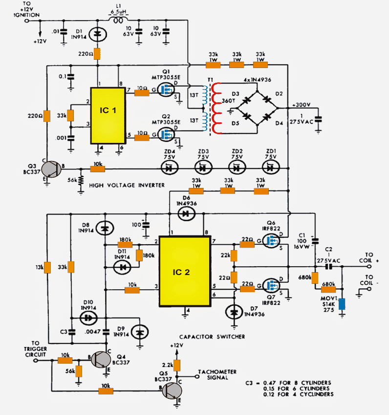
The following diagram illustrates an enhanced version of a multi-spark CDI circuit. Fundamentally it can bifurcated into two discrete stages.
Both the stages incorporate the IC IR2155 MOSFET driver with built in 50% duty cycle oscillator.
The upper stage consisting of Q1, Q2 are configured for generating 300V DC from the available 12V DC input battery supply.
The IC2 along with the connected mosfets Q6/Q7 form a push pull type pump circuit for alternately charging and discharging a high voltage capacitor across the connected ignition coil.
Circuit Operation
IC1 is wired up for oscillating at about 22kHz as per the selection of the 33k resistor and the 102 capacitor across pin2/3 and pin3/ground respectively.
This results in producing alternate switching of its output mosfetsQ1/Q2 connected across pins 5/7.
The above switching performs a push pull reaction over the connected transformer wherein the two halves of the winding are saturated alternately with the mosfet conduction, which results in pumping of the entire 12V DC across the two half winding of the transformer.
This action results in a stepped up induction across the secondary winding of the transformer giving rise to the required 300V AC switched at the 22kHz rate.
The mosfets have their own internal transient protection system built in in the form of 60V zener diodes which limit the internal spikes to 60V safeguarding them from the relevant dangers, also the external gate 10 ohm resistors ensures a relatively exponential charge and discharge of the mosfet internal capacitance thereby reducing noise and disturbance which could otherwise influence the vehicle electrical adversely.
A couple metalized capacitors rated at 10uF are installed in order to decouple DC from T1 so that Tr1 receives the 12V switching optimally across its winding.
The stepped up voltage at the output of TR1 is rectified by the 4 fast recovery type diodes configured as a bridge rectifier.
The ripples are further filtered by the metalized high voltage capacitor rated at 1uF/275V
Even with the all the above high efficiency and protected circuitry, the IC1 stage has no ability os controlling the output voltage in response to the rising and falling of the 12V DC input which normally wouldn't be stable due to the vehicle's speeds and alternator RPM variations.
To tackle this, an innovative transformer output voltage correction feature is Incorporated here using a voltage feedback circuitry involving ZD1---ZD4 along with Q3 and a few passive components.
The four 75V zeners start conducting as soon as the voltage begins drifting above the 300V mark, which in turn results in the conduction of Q3. This action from Q3 results in dragging pin1 voltage of IC1 from 12V to gradually 6V.
Using the Shut Down Option
Pin1 being the shut down pinout of the IC1 alerts the IC to trigger its internal under voltage cut-off feature resulting in an instantaneous shut down of its output pulses which in turn switches off the mosfets for that particular instant.
The mosfets being switched OFF means no output voltage and Q3 unable to conduct which again restores the circuit to its original functional mode, and the operations repeat and rotate keeping the output voltage quite stabilized at the specified 300V volt mark.
Another clever enhancement technique employed here is the use of three 33k resistors feedback loop from the output of TR1 to the IC1 supply pinout.
This loop ensures that the circuit stays functional even when the vehicle is not running at optimal speeds or the supply voltage dropping considerably below the required 12V level.
During such situations, the discussed 33kx3 feedback loop keeps the voltage level to IC1 well above 12V ensuring optimal response even under conditions with steep voltage falls.
The 300V from TR1 is also applied to IC2 which is specifically configured as a high side mosfet driver, because here its output is not connected with a center tap transformer rather a single coil which needs a full drive across its winding in forward reverse method during each alternate pulse from IC2.
Thanks to the IC IR2155 which has all the necessary features built in and effectively starts working as a high side driver with the help of just a few external passive parts C1, C6, D7.
Function of the Ferrite Transformer
The conduction of Q6/Q7 pumps the 300V volts from TR1 inside the connected ignition coil primary via the 1uF/275V capacitor.
The calculated configuration of various components across pin2 and pin3 of IC2 constitutes the intended multi sparks across the connected coil due to the interactions between these components. More precisely, the parts form a timer design with the help of the 180k resistor at pin2 along with the 0.0047uF capacitor across pin3 of IC2.
The 10k resistor and the 0.0047uF capacitor between pin3 restricts over current while it's being triggered by the MMV circuit.
The output from Q5 facilitates a low voltage output for integrating a tachometer in order to provide valid readings on the meter rather than connecting directly to the spark plug.
If in case the multi spark feature seems not so useful or for some reasons inappropriate then it can be successfully disabled by eliminating C3, D10, D11 and the couple of 180k resistors along with the 33k and the 13k resistors. Also by substituting the 33k resistor with a 180 k resistor and a short link in place of D10.
The above mods will force IC2 to generate just single 0.5ms pulses as soon as Q7 is triggered. The ignition coil now fires only in one direction while Q7 is ON and in once in the opposite direction when Q6 is ON.
The associated MOV neutralizes any possibility of high voltage transients in case the output of the ignition coil is left open.
The couple of 680k resistors across C2 provides a safe discharging path for C2 whenever the coil is disconnected from the circuit.
This safeguards the circuit and the user from nasty high voltage discharge from C2.
Circuit Diagram
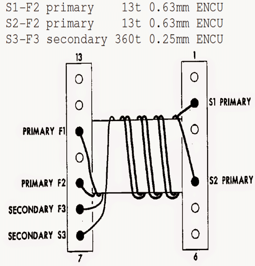
TR1 winding Details:
Start from pin7 (left hand side) using 0.25mm enameled super enameled copper wire as shown in the diagram and end at pin8(left hand side) with 360 turns.
This completes the secondary winding.
For the primary side wind in a bifilar manner meaning wind both the winding together, starting at pin2 and pin4 (right hand side) and ending after 13 turns at pin11 and pin9 respectively (left hand side) using 0.63mm wire.
The bobbin used is for suiting N27 Ferrite Core
L1 is 12 turns of 1mm wire on a Neosid Ringcore 17-732-22
Transformer Design


Comments
Hello good morning, questions about the Trigger signal. Using a distributor of the type (Hall 12v) do I get the signal directly from the distributor or collect the already rectified signal coming from the ignition module?
Hi, Good Morning! A hall sensor gives one clean square wave 0v to 12v every time the rotor turns. That signal is pure and can be used directly as trigger for firing the cdi. But if we take the signal from the ignition module output then it is already processed, and maybe rectified or mixed with back emf or spike from the coil. So that signal is not good and not reliable for triggering cdi. Some modules may give short high voltage spike or even suppress the signal during rev limit.
So we always take the square wave signal directly from hall sensor output pin which switches ON and OFF sharply as the teeth pass. That signal is best to give to cdi SCR or 555 timer or microcontroller which controls the cdi gate.
Hello, I made this circuit with a full ground pour across all components and am having problems with noise. Do you think I should split the ground?
Hi, I cannot find anything wrong with a full ground pour, you can probably add capacitors across relevant points to minimize noise.
excelente idea del CDI la pondré en practica en mi moto a ver si tiene más rendimiento en la velocidad
Glad you liked the design! Hope it works efficiently for your motorcycle.
Hello,
Thanks again for your reply/help so far on several projects. Generally speaking, does adding an air gap require frequency to go up or down? Also it is the windings that are getting hot not the transformer.
Thanks,
Jon
Hi, thanks! Even if an air gap is introduced, still it will require the frequency to match the winding and the core specifications optimally. Without proper matching the core and the winding might either heat up a lot or might become unresponsive. You can try optimizing the frequency and the PWM with some trial and error until an optimal response from the transformer is achieved.
Hello,
Thanks for your response and all your help so far! It is actually the windings of the transformer that is getting very hot not the core. Would an air gap still help? Generally speaking does adding an air gap require an increase in frequency or a decrease in frequency?
Thanks,
Jon
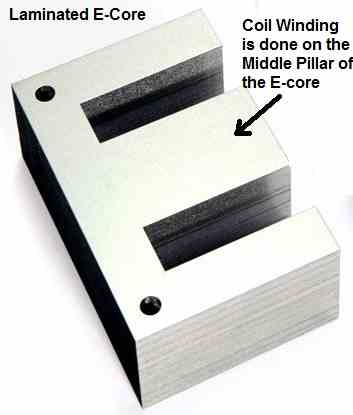
The air gap basically helps to prevent the cores from running into saturation mode. Once saturation mode is hit, the winding is no longer able to resist the current and succumbs to high current passage though the winding causing overheating and burning of the winding. Thus air gap is recommended in all circumstances.
Hello,
I built a version of this using an SG3525 it works very well 🙂 I am using a signal generator to simulate sustained high RPM running. When I do this the transformer gets very very hot. Would adding an air gap potentially reduce the heat buildup? The frequency is ideal after much experimentation. Any idea on a value for an air gap if this would work?
Jon
Hi, Yes an air gap is crucial to keep the transformer from going into saturation mode. You can insert a piece of paper or a plastic insulation tape between the E core edges, to enable the required gap. Other than this, a transformer can also heat up if it is over loaded or if the oscillation frequency is not compatible with the core of the transformer.
I am using IR21531 I think D9 could be activating the shutdown feature of IR21531. IF CT goes to ground on IR21531 it shuts down IC2 will not oscillate no matter what I try.
D9 is reverse biased, so it will not short Ct pin of the IC, but if you think it is causing the problem, you can try removing it….you can also remove D10 if it looks doubtful.
However both these diodes must have been put for some reason in the original circuit.
Hello,
I built this circuit and have a larger transformer that is being used to charge a larger capacitor. I do not have an inductor on this circuit however the circuit is working. I have doubled the current going through the capacitor what would you recommend for a inductor value?
Hi, glad to know the circuit is working. The coil is for preventing sudden surge current or voltage fluctuations getting into the transformer and the mosfets. If possible try to include an inductor with the given specifications….however i am not sure about the value of the inductor and the dangers of not including this inductor.
Ok, would it be ok to run 10 amps of current through a 6.5 uH inductor? Your fast responses are very helpful.
Yes, if you use appropriately rated thick wires for the inductor. A 2 mm wire thickness will probably be enough.
Hello, I made this circuit with some small changes. I am using mosfets with a higher gate charge for Q6 and Q7 and the output oscillator is not working. Could I reduce the 22k resistor at the gate of Q6 to make up for this?
IS your IC1 oscillating and generating the required high voltage?
Yes I am getting a steady 300 volts.
OK, IC2 oscillator configuration is slightly different to IC1. D6 and C1 are crucial for IC2 to work.
Also, IC2 will oscillate only when Q4 is triggered ON.
This is the mosfet I used for Q6 and Q7 https://www.arrow.com/en/products/sihg186n60ef/vishay
would IC2 have enough gate current to switch it on? I can’t think of any other potential issues.
MOSFETs do not require high current for switching, they require voltage for the switching which must be at least around 12V…current can be a few mA, no problems.
Hello,
I am wondering if I can use this chip for both IC1 and IC2 seeing how IR2155 is no longer available. The only issue I see is the non-latched shutdown on the CT pin for the new chip.
https://www.infineon.com/cms/en/product/power/gate-driver-ics/irs21531d/
Yes, according to me you can use the indicated IC in the above diagrams.
Thanks for the clarification. Trying to decipher and translate some of the “standards” can be confusing and disheartening at times. So many standards, yet hardly any standardization.
Cheers,
DaveM
You are right, I appreciate your feedback!
This question pertains to construction of the transformer in this project, which I’m considering building for a couple of gasoline-powered farm tractors belonging to a relative. It has also been a confusing factor when considering other published projects.
I live in the USA, which uses the AWG wire gauge system. Many other parts of the world, notably the UK and Australia, use the metric system for identifying wire sizes used when winding inductors and transformers. My question is, when a metric wire size is specified, such as used in the transformer in this ignition system, is the specification of 0.25mm and 0.63mm wire the wire’s diameter in mm or the cross-sectional area on mm^2?
Is this method of specifying a wire’s size the most common way to specify a wire size? Please help to unconfuse me. Many of the wire conversion tables that I find on the net don’t seem to have a consistent set of numbers. Do the sizes include the enamel coating thickness or only the copper?
Thanks for your help,
DaveM
The 0.25mm and 0.63mm wire indicates the wire diameter in mm, and is quite common way to represent copper wire thickness for winding transformers and inductors. It is including the enamel of the wire, and not just the copper wire. Providing the wire thickness in mm gives a clear idea to the user regarding the size of the wire.
Hi, Firstly this is a really interesting circuit. I was wondering what the purpose of D7, and the 22R resistor + the 22K Resistor were for. I presume D7 is to prevent any spikes from killing IC2 and the 22R resistor to limit the current of the spike. The 22k Resistor to the gate of Q6 and its source I have no clue since internally the mosfet would connect VS (pin6) to HI(pin7) when the top mosfet is turned off ?
My other question would be what is the purpose of the MOV in this circuit too, In most cdi topologies there is usually a diode here pointing towards gnd, is this part of the protection of IC2 ?
Regards, Kurt.
Hi, thanks and glad you found my site interesting.
You are right, D7 and 22 Ohm are included to limit high voltage spikes.
The 22k could be also something to do with the safeguarding of the high side MOSFET, the switching process of the high side FET is not normal and easy like the low side MOSFET, it involves complex bootstrapping.
The MOV is for clamping high voltage reverse transients from the ignition coil
Hi thanks for your quick reply, I looked into this more and I can see the reason for it in the application notes now. I found the same thing on page 10 of this app note https://www.infineon.com/dgdl/Infineon-Using_Monolithic_Voltage_Gate_Drivers-AN-v01_00-EN.pdf?fileId=5546d462584d1d4a01585242c11947b1 Shows clamping the Vs location to gnd and adding a resistor Rvs. I also found another app note https://www.onsemi.com/pub/Collateral/AND9674-D.PDF which shows the advantages of adding a small bootstrap resistor in series with the diode to prevent charge feedback into the vcc rail of the IC. Pages 3 and 4 of this datasheet https://www.st.com/resource/en/application_note/cd00003947-capacitive-discharge-ignition-stmicroelectronics.pdf show the 2 common types of CDI topologies and their output waveforms. I would imagine that the Mov would do a similar thing as the diode in the 2nd topology although perhaps it would survive much better than a diode would if the CDI was fired without the coil present on the output.
OK, thanks for the interesting information, appreciate your feedback very much!
Thanks! I’ve sent you a private e-mail using the contact section of this website regarding help with this circuitry.
Thank you very much for your help!!!
Thanks for your prompt reply! Just copied the part numbers from the schematic as advised, all good!
More questions, sorry! Any ideas on how could we add a programmable rev limiter to this schematic? Also, what are the maximum revs this ignition can handle when paired with a V8 engine? 10K RPM perhaps? What is the expected output in milliJoules 100? 130?
Glad you copy them without issues! you can control the RPM by adding a feedback system as given in the following article:
https://www.homemade-circuits.com/vehicle-speed-limit-alarm-circuit/
The “LOAD” can be removed, and the pin5 of the IC connected with the pin3 of the IC1 of the above circuit.
The maximum capacity can be limitless due to the involvement of the MOSFETs, and ferrite core, so it can be suitable for virtually any motor bike.
Dear Mr Swagatam, thanks for posting this!
Just wondering if you got a parts list available for this project, please?!
Cheers,
Ed
Thanks Ed, you can copy the part numbers from the schematic, if you have any doubts let me know I’ll clarify it quickly.
Dear Swagatam,
i am very interested by the CDI ignition but the parts used for the transformer are not still available. Could you help me?
Thank you for your help.
Regards
Thanks Moes, however sorry I can’t help you with the parts, you will have to search their availability online.
hello,
newbe from france….
where or from who can i get this pcb sc050309971?
i like to restore my old car with this cdi ignition (v8 Ford 302 5lt engine1968 )
i think i still can get all the needed components but my blocage is the pcb….
if any body could help me out on this…. i’m absolutly not an electronic engineer far from that , but this kit sounds right for me to use .
Thanks for any usefull information
Hi, I am sorry there’s no PCB available for this design at this moment. I think you should first build and test it on a veroboard, and get the PCB designed only once the design is confirmed at your end.
Hello,
what type of ignition coil do I use with this multi spark cdi box? high impedance or low? oil filled or e- core type…?
getting lost à bit…. and the wires from box to coil?
many thx
Greetings from France
Hi, you can use any standard iron-core CDI coil with the above circuit.
Hi, just wondering how to adapt this for a positive ground system as in old british cars?
Thanks.
Hi, if you can somehow isolate the whole circuit along with the spark plug from the car body then probably you can use the circuit as is without any changes.
Hello Digital Abacus can you go into further detail for your CDI for your lancer? How does it differ from this design? I am also having difficulties with this circuit specifically Q2.
Hello, I am having that issue as well. Can you share your circuit?
They are both IC IR2155