In this post I have explained a simple, accurate, high torque treadmill motor speed controller circuit which may be effectively installed in similar units for acquiring PWM controlled variable speed feature. The idea was requested by Mr. Samuel.
Technical Specifications
I've a treadmill whose power failed completely...it had been imported from china and it's like they can't help after negotiating with them..guarantee is only meant in their x-try.
So, am asking, how would you assist me in designing a power supply that will control speed and change of direction of the treadmill movement as well. I'm and forever will be glad for your work.
Looking into the specs of the unit, the switching relays are specified with 10A ratings. I also had a view of the motor and it was written 180Volts on it.
This is the information i got sir. They also had a cautionary notice that the T.Mill shouldn't be run beyond 2hrs continuously. I hope I've given the best for the best.Thanks sir. Stay blessed now and forever! best moments!
Using a Single IC 555 Astable Multivibrator in PWM Mode
Audio/Video Representation
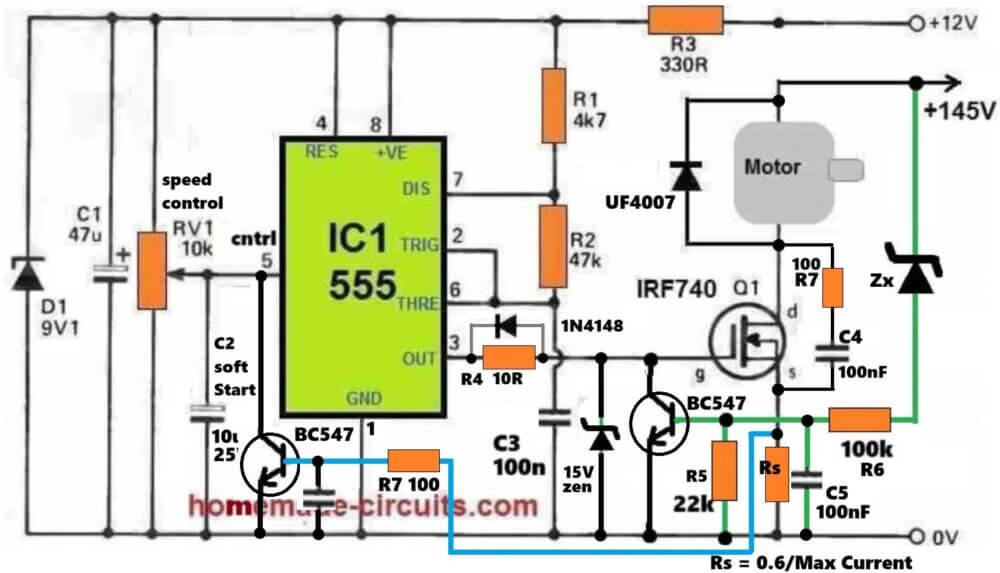
This is a PWM based speed controller circuit for a high voltage DC treadmill motor. The main controller is the 555 timer, which generates the PWM signal and drives the IRF740 power MOSFET. The motor is supplied from a separate +145V DC supply, while the 555 control circuit works from the +12V supply.
12V control supply
The +12V supply first passes through R3 330 ohm. D1 9.1V zener is used to limit the supply voltage for the 555 circuit and C1 47uF provides filtering.
So the 555 gets roughly 9V supply and the high voltage 145V motor supply is kept separate from the low voltage control section.
555 PWM generator
The 555 together with R1 4.7K, R2 47K and C3 100nF forms the PWM oscillator.
The output is taken from pin 3 of the 555 and is given to the gate of IRF740 through R4 10 ohm.
RV1 10K is used as the speed control. Its wiper is connected to pin 5 of the 555. When RV1 is rotated, the voltage at pin 5 changes and this changes the PWM duty cycle.
When the PWM duty cycle is increased, the IRF740 remains ON for longer time and more average power is given to the motor. So the motor speed increases.
When the duty cycle is reduced, the motor receives less average power and the speed comes down.
With R1 4.7K, R2 47K and C3 100nF, the basic operating frequency is around 2.7kHz. The actual frequency can change somewhat because pin 5 is also being used for controlling the PWM.
Soft start
C2 10uF is used for the soft-start function.
When the circuit is switched ON, C2 is initially discharged. Since C2 is connected to pin 5 of the 555, the control voltage changes gradually as C2 charges.
Because of this, the PWM does not suddenly jump to a high level. The motor power increases gradually and the motor starts more smoothly.
This is useful in a treadmill because the motor can take a very high current during starting, especially when the belt is already loaded.
MOSFET gate drive
The PWM output from pin 3 of the 555 reaches the IRF740 gate through R4 10 ohm.
R4 limits the instantaneous gate current and also helps to reduce gate ringing.
The 1N4148 provides a faster path in one direction, allowing the MOSFET gate to charge or discharge faster.
The 15V zener connected between the gate and source of IRF740 protects the MOSFET gate from excessive VGS voltage and switching spikes.
Motor switching
The IRF740 is used as a low-side power switch.
The motor is connected between +145V and the drain of IRF740. Therefore, when the MOSFET turns ON, current flows from +145V through the motor and then through IRF740 to ground.
When the MOSFET turns OFF, the motor current cannot suddenly stop because the motor is an inductive load. The UF4007 then provides the freewheeling path for this motor current.
The UF4007 is a fast recovery diode and is more suitable for this PWM application than the normal 1N4007.
But its actual current and voltage ratings still have to be suitable for the motor. A treadmill motor can draw very high current during starting and heavy loading.
RC snubber
R7 100 ohm and C4 100nF are connected across the IRF740 switching section and form an RC snubber.
When IRF740 switches OFF, the inductance of the motor wiring and other parasitic inductances can produce a fast voltage spike and ringing at the MOSFET drain.
R7 and C4 absorb and damp these high frequency spikes.
So this RC snubber helps to reduce switching stress on the IRF740 and makes the switching waveform cleaner.
Current limiting
The current limiting section works in a different way from the voltage protection section.
Rs is the current sensing resistor and it is connected in the source path of IRF740.
When motor current flows through Rs, a voltage develops across this resistor. The value of Rs can be approximately selected using:
Rs = 0.6 / Maximum Current
For example, if the required maximum motor current is 10A:
Rs = 0.6 / 10
Rs = 0.06 ohm.
The voltage developed across Rs is applied through R7 100 ohm to the base of the LEFT BC547. When the motor current becomes high enough to produce around 0.6V across Rs, the LEFT BC547 starts conducting.
Now the important part is that this BC547 does not directly pull the IRF740 gate to ground.
Its collector is connected to pin 5 of the 555. Therefore, when the current becomes excessive, the BC547 pulls pin 5 of the 555 towards ground. This changes the 555 control voltage and reduces the PWM duty cycle.
The IRF740 then gets less ON time and the motor current is reduced.
This is especially useful during motor starting and when the treadmill is heavily loaded. R5 22K and C5 100nF are used around the sensing section to keep the sensing point stable and filter unwanted switching spikes.
Voltage protection
The voltage protection works separately from the current limiting circuit.
Zx, R6 100K, R5 and C5 are connected to the RIGHT BC547 which monitors the high voltage condition.
Zx is connected to the +145V rail. When the monitored voltage becomes high enough, Zx starts conducting and current flows through R6 into the base of the RIGHT BC547.
When this BC547 turns ON, its collector pulls the IRF740 gate directly towards ground.
Therefore the IRF740 is switched OFF. So the voltage protection action is....This is different from the current limiting action.
The current feedback controls pin 5 of the 555 and reduces the PWM, while the voltage feedback directly pulls the MOSFET gate to ground. The exact voltage protection level depends on the actual value of Zx, so the cutoff voltage cannot be calculated from the diagram unless the Zx value is known.
C5 and R5 in voltage sensing
C5 100nF provides filtering at the base of the RIGHT BC547. This helps prevent short switching spikes from unnecessarily turning the transistor ON. R5 22K keeps the BC547 base pulled towards ground when there is not enough sensing voltage. So this section gives a more stable voltage protection operation.
Complete working
- In simple way, RV1 controls the speed by changing the 555 control voltage.
- The 555 generates the PWM and this PWM drives the IRF740.
- The IRF740 switches the 145V DC supply to the motor and the PWM duty cycle controls the average power given to the motor.
- C2 provides soft start during startup.
- UF4007 provides the freewheeling path for the motor current when the MOSFET switches OFF.
- R7 and C4 form the RC snubber and reduce voltage spikes across the MOSFET.
- The 15V zener protects the IRF740 gate.
- Rs senses the motor current and the LEFT BC547 provides current feedback to pin 5 of the 555. When current becomes too high, it pulls pin 5 down and reduces the PWM.
- Zx and the RIGHT BC547 provide voltage protection. When the sensed voltage becomes too high, the RIGHT BC547 directly pulls the IRF740 gate to ground and switches the MOSFET OFF.
Using Two IC 555
Here's a simple PWM based motor speed controller circuit which can be used for controlling a treadmill speed right from zero to maximum.
The circuit also provides an instant bidirectional stop and reversal of the motor rotation by a single flick of a given switch.
Another interesting feature of this circuit is its capability of sustaining and balancing optimal torque even at lower speeds ensuring a continuous working of the motor without stalling it during extreme low speeds.
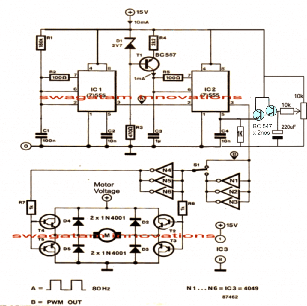
The circuit of the proposed treadmill motor speed controller may be understood with the help of the following points:
Here the two 555 ICs are configured as PWM generator/optimizer for acquiring the required speed control of the connected motor.
Circuit Operation
IC1 works as a frequency generator and is rigged at around 80Hz, any other value would also do and is not anyway critical.
The above frequency from pin#3 of IC1 is fed to pin#2 of IC2 which is wired as a standard monostable. IC2 responds and starts oscillating at this frequency, forcing equivalent triangle wave frequency at its pin2/6.
The above triangle waves is instantly compared by the set potential at pin#5 of IC2 creating an equivalent level of chopped PWM at its pin#3
The preset or a pot positioned at pin#5 of IC2 forms a potential divider network for a selectable fixing of any voltage from zero to maximum supply voltage at pin5 of IC2. This level is directly translated through optimized PWMs at pin#3 of the same IC as explained above.
The PWMs are fed across two sets of NOT gates via an SPDT toggle switch.
The NOT gates which act as inverters provide the feature of instant toggling of the motors rotational direction by a mere flick of the SPDT switch.
The resultant PWMs from the selected NOT gates finally reach the transistorized bridge network that holds the motor between them for implementing all the specified features discussed above.
These transistors should be rated as per the motor specifications, and the voltage across this bridge should also be as per the motor requirements.
Video Clip:
Simplified Design
If you do not wish to have the reverse forward facility, then you can much simplify the above design by eliminating the lower section of the circuit entirely, as shown below:
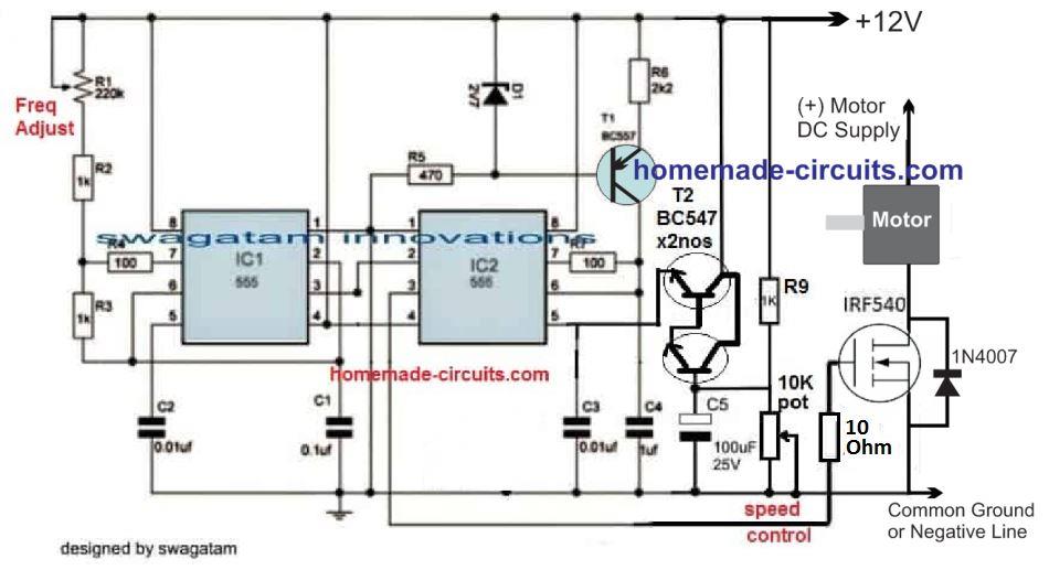
The 10K pot can be used for the speed control, while the 220uF determines the soft start feature. Increasing the 220uF value increases the soft start effect and vice versa.
Controlling Through an External Power Supply
The above design could be also modified for enabling motor speed control through an external variable power supply, as shown below.
Pin#5 can be seen driven from an external 0 to 10V variable power supply, for example from a LM317 based power supply
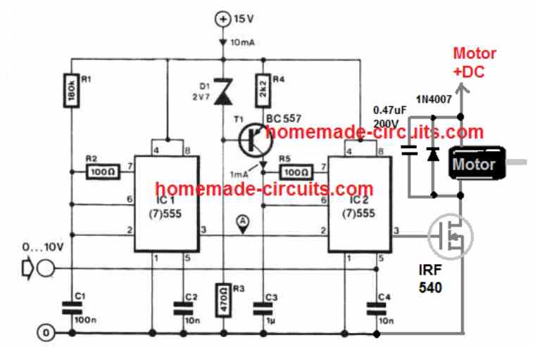
If you do not wish to use an external power supply, the above treadmill speed controller design could be simplified even further, by adding a 1k pot at pin#5 of IC2, as demonstrated below:
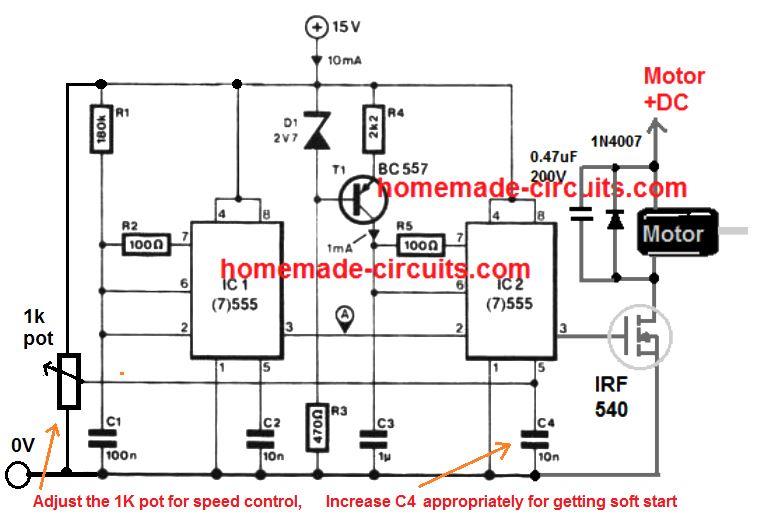
The 1k pot will allow you to adjust the treadmill speed from 10% to 90%, and the C4 value could be experimented to add a nice soft start to the treadmill motor during the switch ON.
Construction Guide
Power Supply Section
15V DC Supply:
Ensure that the input power source delivers a stable 15V DC, because it is critical for the 555 timers and the IRF540 MOSFET operation.
Use a well-filtered power source to avoid the noise interference.
Zener Diode (D1 - 2.7V):
Provides a fixed reference voltage for the base of T1 (BC557 transistor) which gives stable operation.
PWM Generator (IC1 - 555 Timer)
The first 555 timer (IC1) is configured as an astable multivibrator, to generate a pulse-width modulated (PWM) signal.
Pin Connections:
Pin 1 (GND): Connect to the ground.
Pin 8 (Vcc): Connect to +15V supply.
Pin 4 (Reset): Connect to +15V to enable the IC.
Pin 5 (Control Voltage): Add a 10nF capacitor (C2) to ground to stabilize the PWM signal.
Pin 3 (Output): Outputs the PWM signal to the base of T1 (BC557 transistor) via R4.
Frequency Control:
Use R1 R2, and C1 to set the frequency of the PWM signal.
Formula for frequency:
f = 1.44 / [(R1 + 2R2) * C1]Where:
R1 = 180kΩ
R2 = 100kΩ
C1 = 100nF
PWM Adjustment (1kΩ Potentiometer):
The 1kΩ potentiometer varies the duty cycle of the PWM signal allowing the speed control of the treadmill motor.
Soft Start and Motor Driver (IC2 - 555 Timer)
The second 555 timer (IC2), is configured as a monostable multivibrator to implement the soft start feature.
Pin Connections:
Pin 1 (GND): Connect to the ground.
Pin 8 (Vcc): Connect to +15V supply.
Pin 4 (Reset): Connect to +15V to enable the IC.
Pin 5 (Control Voltage): Add a 10nF capacitor (C3) to ground.
Pin 3 (Output): Drives the gate of the IRF540 MOSFET.
Soft Start Capacitor (C4 - 10nF):
This capacitor determines, the ramp-up time for the soft start feature.
Larger values of the C4 increases the soft start time.
Adjust C4 using the formula:
t = 1.1 * R6 * C4Where:
R6 = 10kΩ
C4 = Soft start capacitor
Motor Connection:
The motor is connected to the drain of the IRF540 MOSFET with the source connected to the ground.
D5 (1N4007): Protects the MOSFET from back the EMF generated by the motor.
Working Principle
PWM Speed Control:
The duty cycle of the PWM signal generated by IC1 provides the average voltage applied to the motor.
Adjusting the 1kΩ pot, changes the PWM duty cycle effectively, controlling the motor speed.
Soft Start:
When the circuit is powered ON, the IC2 gradually increases the gate voltage of the MOSFET due to the charging of the C4.
This ensures that motor starts smoothly without jerks.
Overvoltage Protection:
The 2.7V zener diode (D1) ensure the PWM output voltage doesnt exceed safe levels for the transistor T1.
Relevant Calculations
Frequency of PWM Signal (IC1):
f = 1.44 / [(R1 + 2R2) * C1]For the given values:
R1 = 180kΩ
R2 = 100kΩ
C1 = 100nF
Substituting:
f = 1.44 / [(180k + 2 * 100k) * 0.1µF]
f ≈ 34.3 Hz
Soft Start Time (IC2):
t = 1.1 * R6 * C4For the given values:
R6 = 10kΩ
C4 = 10nF
Substituting:
t = 1.1 * 10k * 10n
t = 0.11 ms
If a larger value for the C4 is chosen (e.g 1µF):
t = 1.1 * 10k * 1µF
t = 11 ms
Assembly Tips
Use a Heat Sink for the IRF540:
The MOSFET can heat up under heavy motor loads so Attach an appropriate heat sink.
PCB Design:
Keep the ground connections of the IC1, IC2 and the motor driver separate to avoid noise.
Testing:
Test the PWM output with the multimeter or oscilloscope before connecting the motor.
Safety Precautions:
Ensure proper insulation for all tthe high-current connections to prevent short circuit.
Using A Dimmer Phase Chopper Circuit
As rightly suggested by one of the dedicated readers of this blog, Mr. Ivan, a 180 V treadmill motor can be simply controlled through mains phase chopping concept, normally incorporated in all commercial dimmer switches for regulating home fan speed.
Shown below is a modified dimmer switch circuit design which can be effectively used for regulating a 180 V treadmill motor from zero to max:
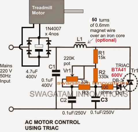
Please make sure to use a non-polar capacitor for the one shown between the bridge rectifier.
Use the following type, 10 in parallel
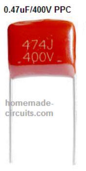
10nos of 0.47/400V in parallel will make 47uF/400V non polar capacitor which may work like a decent filter capacitor for the motor.



Questions & Answers
Hi, Could you explain how a constant torque at low speeds is achieved? My treadmill bogs down slightly with each step when I get below about 1.2mph.
Constant torque is achieved by the use of PWMs which prevent the devices from unnecessarily heating up yet allowing them to conduct fully during the ON states of the devices.
So it's like allowing the devices to conduct fully with full power yet only at the desired slower speeds by breaking their conduction many number of times per second.
Hello
My treadmill motor is rated for 130VDC and 15a. I plan on using 120vac(line voltage) and a bridge rectifier to power the motor. What type of transistors would I use for T2-T5? I don't recognize the symbol you used. IRF540 mosfet is only 100v, I think. any advice is welcome.
Also, what is the symbol just left of C1? I apologize for my lack of knowledge.
Hello,
You can use MJ11021(PNP) MJ11022 (NPN) for the transistors
It indicates the (0) volt line or the negative volt line.
I'm putting together a shopping list for this project. 1/4 watt metal film resistors would work, right?
C3 is listed as 1uf, what voltage and style of capacitor should i get? The other caps I was going to buy 50VDC ceramic disc. My motor is rated at 130VDC 15A, i was going to power the motor with 110VAC thru a bridge rectifier, any ideas on what transistors to buy? IRF540 is only 100volts One last thing, what is the symbol just left of C1? I apologize for my lack of knowledge.
BJTs are easier to handle than mosfets, so it's better to use BJTs here.
Thank you for your replies. I have all the part numbers figured out and I am excited to build this circuit. This is an amazing site and appreciate the time you dedicate to helping others. Thank You.
You are welcome!
Thanks for the great design! Why are the BJTs better here, as I understand BJTs are preferred for low current applications, while MOSFETs are for high power functions.
Thanks,
Matt M
If the requirement is above 30 amps mosfets could be preferred…mosfets require stricter parameters while configuring compared to BJTs therefore sometimes become difficult to handle.
however in the above design mosfets could be used since the configuration does not demand a high side driver due to the involvement of both n/p mosftes..
Thanks for this fantastic circuit diagram. I'm new to electronics so please excuse me if these are dumb questions. Would there need to be any programming done to make this work or does the hardware do all that automatically? Also, I wouldn't need the reverse feature and a simpler circuit would definitely be easier for a beginner like me. Could you show us what this circuit would look like without the components necessary for the reverse feature and how I could make this work using 110vac i.e. Where would the ac come in and where would it be rectified? Thanks again!
Thanks very much Michael, no programing is required for the devices all the ICs come preprogrammed, just have to wire them up in the shown manner.
If you are not interested in the reversing feature the circuit definitely becomes much simpler as shown in the following image:
1.bp.blogspot.com/-jONLYQ8Ehro/UkD_gzAjA-I/AAAAAAAAFSk/nt6vxMDF9RU/s1600/ELC+circuit.png
ignore the four diodes shown at the top which was drawn for some other similar application need.
the mosfet upper lead which is drain needs to be connected with the motor negative, while the positive of the motor will connect with the 110V DC or whatever may be the motor operational voltage spec.
The circuit would however need to be powered through a 12V AC/DC adapter specified to take the input from a 110V AC, nowadays such adapters are suited for any input right from 85V AC to 285V AC, so it won't be much of a concern
The shown pot could be used for the required speed control.
Excellent. Thanks!
what is D1 is it a zener diode
yes it's a zener diode.
im sorry one more, R4 is that 2.2k or 2002 ?
it's 2.2k
Many thanks Sir for this publication.
I'm sorry for dump questions but I'm newbe to electronics.
Will this work with my 240VDC/12A motor?
How many of this CD4049UBE CD4049 4049 IC Hex Buffer/Converters do I need to order?
Regards,
Wes
My pleasure! yes it'll work with the specified motor, you'll need to use high voltage BJTs for it as given in the following datasheet:
https://www.homemade-circuits.com/2014/04/mj11021pnp-mj11022-npn-high-voltage.html
Only one 4049 IC is required for the above design
Thanks a lot!
Dear Swagatam, many thanks for your fast replies.
I’ve managed to put everything together and pluged in. Unfortunatelly when my treadmill motor (220VDC/3.5hp)
started to turn a smoke come out from one of the BJTs.
Now it looks like all four of them (mj11021pnp-mj11022-npn) has gone, cos I can’t see any reading between base-collector, emitter when testing them.
What I’ve noticed afterwards that it was a bad solder between R6 and bases of T2,T3.Virtually no connection at all. Also I’ve used 1N4744 as a D1.
What do you think Sir. Any suggestions?
Regards, Wes.
Dear Wes,
A bad solder won't cause a burning problem according to me, I think the treadmill motor could have exceeded the max amp rating of the BJTs,
Replace the circuit with new transistors and try operating the treadmill without any load, check the response,
the other reason could be wrongly configured BJTs
….1N4744 are zener diodes and will never work here, you'll have to use rectifier diodes such as 6A4 etc.
this could be an issue too
Many thanks Swagatam.
New high voltage transistors just been ordered. You're right. After closer examination it looks like BJTs were wrongly configured. This cause them to burn.
So do you think that I could use four 6A4 rectifiers in the bridge instead of 1N4001 as it is in your cuircuit?
Talking about Zenner diodes, I'm using 1N4744 instead of 2v7 as a D1 which is a Zenner diode in your circuit. I don't use them in the bridge.
Regards Sir,
Wes
OK Wes, that's good! yes 6A4 is the minimum requirement for the bridge diodes, 1N4001 will not do as these will blow of due to the high motor back emf.
I mistakenly thought that you had used the zener in the motor bridge circuit,….surely it will do in place of the shown 2.7V zener
Many thanks Sir. Now it looks very promising.
Regards,
Wes
You are welcome!!
Mr. Majumdar, I have a similar problem. I have a treadmill which controller chip has failed and now i would like to build independent control of the motor. It is PMDC (Permanent-magnet DC) motor, 180V, 6.8A. I want to control it's speed from zero to max by powering it from 220V AC power grid. Can you give some circuit similar to the above one, but for 220V AC, please?
Hi Ivan, you can try the following simple design
https://www.homemade-circuits.com/2012/05/make-this-pwm-based-dc-motor-speed.html
Just make sure that the circuit supply is acquired from a 12V AC/DC adapter while the motor terminal from a 180V Dc (+) source
The (-) of the 180V must be made common with the (-) of the 12V supply or the (-) of the circuit
The 180V could be achieved through a half wave rectification using a single 6A4 diode and filtered using a 10uF/400V capacitor.
The MOSFET should be an IRF840
Thanks for the reply, Mr. Majumdar, but the circuit you offer uses PWM. How about just changing the gate voltage in order to control the drain current? Is this possible and which way is the best?
Hi ivan, It's not possible to control a mosfet drain load with a varying gate voltage, PWM is the easiest and the most ideal way of achieving the intended speed control through a mosfet.
Thanks, I'll do it!
Hi, Mr. Majumdar, I did exactly as you told me – a half-wave rectifier with 6A4 diode and a 10uF/400V capacitor, but the voltage between the poles of the capacitor is 325V DC!
Hi Ivan, it's showing the peak voltage, once connected to the load the voltage will come down to the specified level, however still it could be not so safe to apply the pulsating peaks to the motor, so I think you will have to get a suitable auto-transformer designed from a transformer maker. Tell him to design a transformer which would be able to supply 150V/6amp from 220V….this output can be then bridge rectified and filtered to acquire the required 180v for your motor.
Sorry for my last post, I knew that this is the peak value of the voltage formed by the capacitor, but the post was already on its way. At all I intend to use this circuit:
2.bp.blogspot.com/-wJnI3vNWGoo/UoxAV_X6LyI/AAAAAAAAFxU/7NZJ4A2bg88/s1600/treadmill+motor+speed+controller+circuit.png
I have also some differences – I need one direction and have 180V DC motor at 2.2HP (that's 1640W of power). It seems that the circuit must be without those NOT gates because of the single way rotation and I'll need only 2 power transistors (in parallel oor in sequence). I don't know only what should be those Darlingtons?
Yes, you are right the NOT gates won't be required in the referred diagram.
For the transistor you can simply use a single high voltage Darligton transistor such as ST901T with pin3 of IC2 for the required implementation.
Just a single ST901T?! I have 1640W of power which makes around 9A of current at 180V and the Icmax of ST901T is just 4A?! The motor will not be loaded at the maximum power rate but still isn't 4A too less? How about 2 or even 3 ST901T's in parallel?
sorry it won't work, I seems I missed the amp spec of the device.
you can either search for a suitable single device or connect many of these in parallel, just make sure all of these are mounted over a single common heatsink.
Hi any possibility a ready made controller can be purchased. I do not have a knowledge about electronics and am desperate in powering up my treadmill.
Hi, I wish I could help by doing it for you, but I am sorry, presently that looks difficult due to lack of time.
Hello, mr Majumdar, I have something much simplier in view with respect to 180V DC treadmill motor control powered from 220V AC grid. The parameters are:
– 220V AC power grid
– 180V permanent magnet DC motor 7Amps motor
– main control element a SCR (thyristor) simultaneously acting like rectifier and control element with phase controlling circuit
– a capacitor in parallel after the thyristor acting simultaneously like smoothing element for the phase-cutted sine and voltage-raising capacitor (just like in the last circuit you offered me).
– a SCR control circuit that uses phase-cut method – cutting the sine at different angles in order to get different voltage values above the motor.
I think it will be much simpler than the two 555 timers PWM and Darlington stages.
Best regards!
Hello Ivan, yes that's a smart idea, since the load is 180 V rated using a dimmer switch circuit as the speed controller is definitely possible, the motor output will only require a bridge network and filter capacitor for the AC to DC conversion.
If possible I'll try to update the design in the above article soon.
Your work will be highly appreciated because I'm trying to run this treadmill for 4 months. An easy-to-build and cheap solution will be more than a good result for me.
I have updated the required diagram above, please check it out.
Thanks, mr. Majumdar, one more question, what diameter should the iron core of L1 have?
Thanks Ivan, The diameter of the core could be such that it accommodates the 200 turns comfortably, it could be done over an iron bolt or screw…but the diameter of the wire should be more than the indicated 0.6 mm since the motor is rated to carry high currents…a 1.5 mm could be tried initially.
Hi, Mr.Majumdar, the dimmer circuit simply does not work, I did 3 times, the load works always at the grid's voltage (220V), no matter the potentiometer setting. All the elements are the same as required, the circuit has been checked maybe 30-40 times, everything is correct but it doesn't work. I also did a circuit with PWM and a MOSFET, the same fails everytime at nearly half turned potentiometer and the engine is even at idle.
I never imagined that controlling the speed of a DC motor can be so difficult!!!
Hi Mr. Ivan the first circuit has been tested by me and it worked right at the first shot, so it surely works, but all these can be difficult for any newcomer i can understand that.
in the second circuit, remove the motor, the bridge diodes network..verify the circuit using an AC lamp as shown in the following lamp, if this doesn't work will mean your circuit is faulty somewhere
1.bp.blogspot.com/-s2Fe-xTv4YA/T4V-Z597HLI/AAAAAAAABFk/mafeMQ6JYm4/s1600/How+to+Control+AC+Motor+or+a+Ceiling+Fan.jpg
connect a 100 watt bulb in place of the "AC motor" in the above link
Mr. Majumdar, I didn't say anything about your first circuit, at least my was with MOSFET stage unlike yours. As for the second one, I tried alll the things you said – removing the engine and the bridge and using a 100W lamp as AC load. The result was the same. Anyway . . . . Now I found another circuit in one of our old elctronic magazines (I'm from Bulgaria). Unlike your second circuit it uses thyristor (SCR), not triac.
postimg.org/image/49kyj0io3/
It's used for drill machines and can power a engine up to 800W. The list of elements is in bulgarian, that's why I'm not posting it here. As in the circuit above, a bridge rectifier and a smoothing capacitor should give my treadmill DC motor what it needs . . . . . I hope.
Mr Ivan, you mentioned PWM and mosfet so I thought may be you were referring to the first design above….
anyway the second circuit is a very basic fan dimmer switch design that we use in our homes for controlling fan speeds or light intensity….i have tested the circuit thoroughly and have one installed in my house….so if an AC load is not working in your circuit then definitely there's something incorrect in your circuit assembly.
The image that you ahve provided will controll speeds upti 50% only and will create lot of jerk at lower speeds….i already have a similar design posted in my blog here:
https://www.homemade-circuits.com/2012/01/how-to-make-versatile-closed-loop.html
I thought the thyristor will work like half-wave rectifier together with the phase cut-off process. This is because of the voltage differences of the grid and engine (220V and 180V respectively). A lot of these circuits are widely used for motor speed controls. By the way the author of the circuit I uploaded says that the C1 capacitor's value is determined experimentally (between 1 and 10 uF) to choose less jerk and max torque (something like compromise between both). If nothing happens with my circuit, I'll do your first one.
I have another question – what will happend if the value of the pot increases rapidly when the engine goes at slow speed? By my opinion the voltage above the engine will also increase the same way and the power element (SCR, transistor) will fail immediately. I mentioned that the treadmill has opto-tachometer originally. I think it gives feedback to the controller about the current speed of the engine no matter what is the speed set by the user. The speed of the motor will equalize with the speed set by the user, but slowly which prewents this rapid change of the voltage/current. It would be great to implement the tachometer in your first circuit in order to prevent overload of the transistors when the pot shaft is rotated sharply.
Best regards, Ivan!
It would be interesting to check the second circuit also, first by confirming it with an AC bulb and then reverting with the shown bridge network
a tachometer can be avoided by simply adding a resistor/capacitor network at pin5 of IC2 which will slow down the change regardless how fast the pot or the voltage is varied
So, what should those R and C be? From pin 5 capacitor and resistor in sequence to the gound? What should their values be? Does the C4 (10nF) stay at it's place in that case?
Thanks in advance!
i'll try to update the info in the diagram soon…
done…please check it out
I think I got the idea – the RC group together with BC547 works like a time-delay stage so the voltage change from the pot comes to pin 5 delayed depending on the values of R and C. That's smart!
I need few answers:
1. How about the power stage? Will a single MJ11022 be enough as a power stage.I am about to use a ST901T as a preamp stage and two MJ11022 as power stage.
2. The motor voltage is 180V and the grid's voltage is 230V AC. If I use a full-wave rectifier and a smoothing capacitor the rectified voltage will be above the motor's and even transistor's allowable. The other way is to use half-wave rectifier (single diode) and a capacitor behind it in order to get smoothed voltage with the value motor needs. Should I use some bigger capacitor (the original board had a 470uF/400V one). Can I use it again? As long as I know a capacitor's capacity is determined proportional to the load's current.
Please answer all my questions!
a preamp stage is not required, the power device can be directly linked with pin3 of the IC….as shown in this example design:
1.bp.blogspot.com/-jONLYQ8Ehro/UkD_gzAjA-I/AAAAAAAAFSk/nt6vxMDF9RU/s1600/ELC+circuit.png
no matter how 220 v is rectified the result will be always dangerous for the lower rated motor….one solution would be to use a 50 V lamp in series with the motor in order to absorb the extra 50V, the ampere rating of the lamp should be identical to the motor…
Yes, but the original board was also powered by 220V without any lamps or otger resisting elements. Rather I was meaning that all the circuit can be set to power the motor to 180V only no matter what the grid voltage is – with other words we have 220V, but the power transistor passes only 180 of them at maximum turn of the potentiometer.
The circuit from the link you posted is with MOSFET, there's no problem to drive it directly from the IC, but in the first circuit above power Darlington BJT's are used. I don't intend to use MOSFETs anymore.
""no matter how 220 v is rectified the result will be always dangerous for the lower rated motor….""
Why?! Do half-wave and full-wave rectification give one and the same effective value of the rectified voltage?! You said in one of your posts above:
""The 180V could be achieved through a half wave rectification using a single 6A4 diode and filtered using a 10uF/400V capacitor.""
Exactly that was my second question. That's why I want to get clear everything before start to build the circuit. Thanks!
These are PWM circuits they don't control voltage rather the RMS value… in other words it controls the average voltage by breaking the input into a calculated ON/OFF sequences, but the peak voltage always remains equal to the input, that's why it could be dangerous, initially I suggested using a single diode method considering the small difference between the motor and the mains voltage levels, but it's always good to be on the safer side and therefore the peak voltage issue must also be considered.
whether it's a full wave or half wave, the input peak again would be equal to the supply mains input.
a buck converter concept must be incorporated for dropping the voltage or the other short cut method would be to use a series 50 v lamp
A buck converter . . . . Would you post a proper simple circuit of it for my case (which is the case of the theme at all). Embedding it into the main circuit will give it a finished look.
Thanks in advance!
there's another way of keeping the voltage under control, as shown here:
4.bp.blogspot.com/-zEbdlZt9sTo/VEoQWzsHz5I/AAAAAAAAIfs/p53qd3foLaA/s1600/voltage%2Bcontrol%2Bfor%2BIRS2453.png
the collector of the transistor should be connected with the base of the "blue" BC547 in the first diagram.
The 220k should be adjusted such that transistor in the above link just begins conducting at 190V, an additional 22k preset could be used in series with the 220 k on the input side and used as a fine control preset
in the link above a bridge can be seen, which could be replaced with a single diode from the 220k preset upper lead to the 220V DC
And how about a buck converter with flywheel circuit, just like in the link below?
postimg.org/image/vv40maqnj/
We already have a PWM controlled power transistor, all that remains is just the flywheel circuit (a diode, inductor and a capacitor). As long as I can see it will provide directly 180V from the 230V rectified AC grid voltage in the power line. Would you provide such circuit, mr. Majumdar? Please!
The shown design can be used for your application…you can drive the buck transistor through any high frequency oscillator configuration
an example circuit can be witnessed here
https://www.homemade-circuits.com/2014/06/solar-panel-buck-converter-circuit-with.html
just make sure that the drain of the mosfet is isolated from the R1—R5 positive line and gets separately connected with the 300 DC rectified source.
The positive line of R1—-R5 must be connected with the above 300V DC lien through a 100k resistor and a 12V zener attached across the positive R1—R5 positive and the common ground.
IC1 stage may be ignored and removed….D2 could be replaced with a 200 V zener diode.
sorry, it's not the drain rather the source of the mosfet that should be isolated and connected to the 300V DC source….
Thanks for the example but . . . . the transistor you mentioned in the part list is "Q1 = ANY 100V, 20AMP P-channel MOSFET". Are 100V enough for Q1 in my case?
How about C3 (the reservoir capacitor) from the link? In the part list it is 100uF/100V one. I think in my case it should be at least 400V. And is 100uF capacity enough?
Thanks in advance!
No, for your application the transistor should be 300 to 400 v rated…the filter capacitor will also need to be rated at 400 V minimum….100uF is sufficient because the filtration level is not critical for the speed control functioning.
does cap on schemetic what voltage should they be on? example 10uf should it be 100v or 220v or 400v? confuse sorry still learning the symbol
in the first circuit those are 25V rated since the supply is 12 to 15V
Any possibility contact you in skype or phone? or txt msg i had 3 mc2100ls rev controller for treadmill <,< is fried <,< so i gonna make one my own my motor use 130v and 10amp.
i feel more comfortable interacting through my blog…
couple question base on the image here the link i.imgur.com/IxaxT14.png
Appreciate your time.
diode is a zener diode
all the caps are 25V rated
N1—N6 are the gates from the IC 4049, refer its datasheet for a clearer view
I have read all those post and many picture of schematic I have Permanent Magnet DC Motor with specs of Volts 130 , AMP 10.0 . HP 2.5, RPM 4500, Rotation CW, Duty Continuous. Which of your diagram should I use to power this motor and use 10k pot to control from 0 to max and I would like a reverse on motor can DPDT switch will do? any pointer would help. Thanks for all your time.
you can try the first diagram for your application but you should have an access to 130V Dc for supplying the motor via the transistor bridge
an ordinary SPDT switch will be enough for the reversal
Thanks for the help. Sorry i'm still learning electronic circuit. Here some more question i.imgur.com/MPDZgep.png on schematic.
My kind request to you is not to proceed with this project, you seem to be extremely new to electronics, and this project is not for the newcomers with no prior experience.
everything is clearly shown in the diagram if you are unable to read the symbols you need to study the basics first and proceed gradually.
I clearly Understand the circuit is just that some symbol look different I'm working on proteus 8 and stimulating it in order to build the circuit. here a link of my half work so far. That why i'm asking the property value and which you used for the project that work and from there I cant experiment. i.imgur.com/VP0JdCE.png
Alright I have become more knowledgeable with symbol. I was though different symbol at my class and realize American standard symbol and Europe symbol look very different. anyway I redraw the diagram from Proteus and wanted to have you look it over and see if i'm missing anything feel free to edit it. i.imgur.com/NHR9ug3.png
Question The VCC is 15v but wasn't sure if it's DC or AC on your schematic. I'm almost done getting all parts from ebay to put it together.
The diagram looks OK, except the transistors in the bridge…you'll need to swap T4/T5 and T2/T3 positions. meaning T5 will move to T4 and vice versa, same with T2/T3. In other words the upper transistors should be NPN and the lower ones PNP.
electronic circuits always work with DC, never with AC, so the 15V is DC…preferably use 12V DC.
alright I appreciate your help. Would 1N4007 would do it?
where? inside the bridge?
you can try 1N5408
This seem lot better? i.imgur.com/dG5wInu.png
should i change the diode to 1n4007? or is fine what it's for 130v motor?
the diode polarities inside the bridge is incorrect, it should be exactly as given in my diagram.
You can try 1N5408 instead of 1N4007
Hello Mr. Majumdar,
I want to build this diagram for my bench lathe. Could i use it for this? On the nameplate of the lathe it says 220 Volt 800 Watt and i know that it is a DC motor. If so wat for components should i use for T2…T5 and for D2….D5?
Hello rookie,
you can rather try the following circuit which is relatively simpler and will be suitable for your application:
https://www.homemade-circuits.com/2014/09/automatic-pwm-door-openclose-controller.html
Thanks for the quick reply.
But the other diagram also includes a 12 volts dc motor and on my lathe is a 220 volt dc motor. I want to use a rectifier and a capacitor for the power supply of the motor direct from the wall outlet. If i replace Q1 for another, could i feed it directly the 220 Volt Dc? And do you have a proposal for the Q1 replacement?
yes you'll need to replace the 12V fet with a 500V fet….probably an IRF840 would do the job.
The rectified positive of the 220V will need to be applied at the junction of D3 and the switch making sure that it's been first perfectly disconnected from R2 and the 12V supply line
the negative from the rectifier will connect with the negative of the circuit.
P1 will need to be connected with an appropriately dimensioned series resistor so that the max voltage to the motor is restricted at 220V, because the rectified voltage could be well above 300V
Thank you very much, i will try to start building this weekend or maybe next week. I will let you know how it is going.
Great, You are welcome rookie!
Hello, I have build the diagram but when I turned it on the motor started to turn but I could not control it. I think it has something to do with the IRF840 I used. According to the datasheet of this it has a build in diode so it lets the DC power go straight thru in one direction. I've tried to put the power in the other way but then it blow out the other diode D3. Do you have any idea what to do?
Kind regards
Rookie
Hello Rookie, referring to the following circuit:
https://www.homemade-circuits.com/2014/09/automatic-pwm-door-openclose-controller.html
initially don't connect the load or the 220V AC, just power the circuit with 12V and check the gate voltage while varying the pot.
The voltage must show a corresponding 0 to 12V variation, if this does not happen would indicate either a faulty IC or connections,
the diode inside the mosfet has nothing to do with its performance, it's there for protecting the device from transients and back EMFs.
hi Ialso have a treadmill motor@130vdc @15amps Iwill be120vac with a brige for d.cv and feeding the ic with 0-18 vdc after wiring and putting in all the parts needed, my question is where dose the 130vdc come from to hook up the motor???
The 130v will come from your mains AC outlet after rectifying it through a bridge diode network, although it would become 150V after rectification, can still be used for a 130V motor considering the regulation feature available with the circuit.
…the motor connections and the voltage for the motor are clearly indicated in the first diagram.
thank you for the reply: after it is rectify I have to go throught the 556 ? but I cant the ic can only take 18vdc ,130 will fry it????
you can employ a 12v AC/DC adapter for powering the ICs separately, and make the negative common with the 130V DC
hi I am really missing something here, so the 130vdc dosent go throught the circuit, so then how is it hook up, ??? the 130vdc thank you
it's clearly shown in the diagram, the point indicated "motor voltage" should be applied with the 130V positive, and the negative to the lower rail of the bridge….all the negative or the earth symbols must be made into a common line.
ok so just connect the 130dc on the plus where the motor is connected and the – to 0 rail : I don't understand how the motor would get the pluses. thank you swagatam