A tap water heater circuit can be simply built by attaching an iron tube on the mouth of the tap or the faucet, and allow the iron pipe to pass through an induction heater coil. The induction heater will heat up the iron pipe and hence water passing through the the pipe will also heat up and provide a warm water for the user from the other end of the pipe.
Materials Needed
To build this project you will need the following basic materials:
A ready made induction heater circuit that can be powered from a 12V 10 amp SMPS DC power supply.
An appropriately fabricated metal pipe with Bakelite holder at one end which can be clamped to the tap mouth.
An appropriately dimensioned Bakelite box for enclosing the induction heater, the induction coil, and the metal pipe.
The Set Up
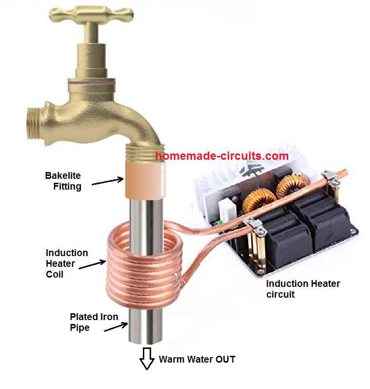
The complete set up for the induction tap water heater circuit can be witnessed in the following set up diagram:
In this set up we can see a plated iron pipe or a galvnized iron pipe is clamped to the mouth of the tap via a bakelite adapter cap. The bakelite cap ensures that the heat from the iron is not able to disperse to the tap metal, and remains instact within the iron pipe.
The iron pipe can be seen encircled by the induction heater coil, or in other words the iron pipe is allowed to pass through the induction heater coil.
The metal pipe diameter must be selected to ensure that the amount of water passing through it is not too large, and the water is able to get warm enough while passing through the pipe. The water coming out from the pipe must be at least 35 degrees Celsius warm.
How to Enclose the Whole Set up
The above explained induction tap water heater circuit set up will need an appropriate enclosure which must be light, sturdy, water proof, heat proof, and could be attached to the tap system along with the iron pipe.
An example format of the enclosure can be seen in the following image.
The enclosure should have ample ventilation from the bottom side, so that the parts of the induction heater can dissipate the heat comfortably without getting too warm.
The power to the induction heater circuit enclosed inside must be supplied from an external SMPS unit, which may be rated at 12 V 10 amps.
Using the SMPS unit externally provides the user with an advantage of using the SMPS for some other desired purpose, when the heater is not being used.

Cheaper than Commercial Water Heater
If you compare the above induction based tap water heater circuit with commercially available geysers and water heaters you will find that the above set up is much cheaper and cost effective than the commercial units.
The complete set up can be built in less than $20, which is 50% less compared to the commercial units.
Also, the electricity consumption can be 50% less for the above explained concept, compared to the commercial heater units, which depend on heater coils rather than induction heating system.
Moreover, you get a free SMPS device which you can use for lighting LEDs, driving a power amplifier or a subwoofer amplifier, a benefit you can never get with the commercial heater units.


Comments
Dear Swagatam,
I think I have written a couple of times regarding this very type of thing. I haven’t seen a reply to them. I was thinking that using the 60hz house current around a pipe would work. I have bought the 12 v induction heater circuit and used it around a pvc pipe with a stainless steel scrubbie in the pipe. It did heat the water ok. What I would like to know is how many turns of copper wire I should use that would give the same effect with house current or maybe I’m just not understanding how an induction heater works.
Thank you,
John
Dear Swagatam,
Can I have more details of the induction coil. Where can I purchase it in India. Soecifications of the induction coil etc.
Thanks
Dear Ashok, you can try any 300 watt ZVS induction heater which may be available in any electronic retailer or online stores like amazon, bangood, robu etc.
Iron or other metal makes very little difference. It is largely the electrical conductivity that an induction heater uses.
It has to be iron, otherwise induction heating cannot take place. The core has to be magnetic otherwise induction cannot happen.