• Skip to main content
  • Skip to primary sidebar

Homemade Circuit Projects

Need circuit help? Post them in the comments! I've answered over 50,000!

Blog | Categories | About | Hire Me | Contact | Calculators-online
You are here: Home / Archives for Explained

Explained

12 Simple IC 4093 Circuits and Projects Explained

Last Updated on January 18, 2025 by Swagatam 10 Comments

4093 piezo driver circuit

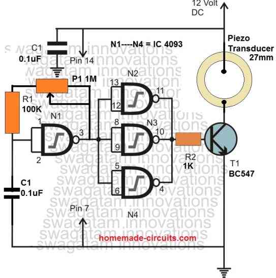
The 4093 is a 14-pin package containing four positive-logic, 2-input NAND Schmitt trigger gates as shown in the following figure. It is possible to operate the four NAND gates separately or collectively. The individual logic gates of the IC 4093 works in the following manner. As you can see each gate has two inputs (A […]

Filed Under: Mini Projects Tagged With: 4093, Circuits, Explained, Projects, Simple

Audio Clipper and Compressor Circuits Explained

Last Updated on January 18, 2025 by Swagatam 25 Comments

audio clipper circuit

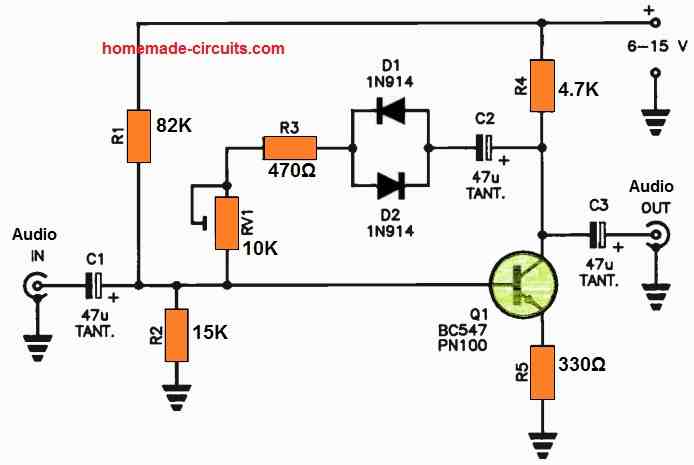
In this article I have explained using circuit diagrams how a clipper and a compressor circuits work to processes an input audio signal as per the required output signal. What is an Audio Clipper An audio clipper circuit is basically used to alter or restrict the amplitude (volume) of an audio signal. There are mostly […]

Filed Under: Audio and Amplifier Projects Tagged With: Audio, Circuits, Clipper, Compressor, Explained

10 Simple Unijunction Transistor (UJT) Circuit Diagrams Explained

Last Updated on January 17, 2025 by Swagatam 21 Comments

UJT Pulse Generator

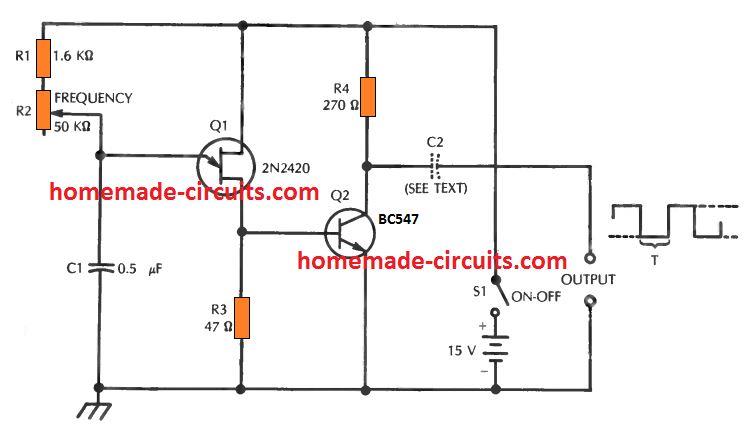
In the earlier post I have explained comprehensively about how a unijunction transistor works, in this post I will elucidate a few interesting application circuits using this amazing device called UJT. The example application circuits using UJT which are explained in the article are: 1) Square Wave Pulse Generator The first design below demonstrates a […]

Filed Under: Oscillator Circuits Tagged With: Diagrams, Explained, Simple, Transistor, UJT, Unijunction

10 Easy Op-amp Oscillator Circuit Diagrams Explained

Last Updated on January 17, 2025 by Swagatam 5 Comments

formula for calculating C1 and L1

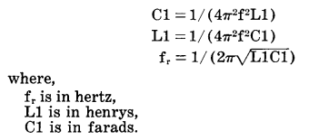
In an op amp oscillator circuit, an op amp is configured with a resistor-capacitor feedback loop or a inductor-capacitor feedback loop, which triggers the op amp to go into an oscillating mode, generating a switching ON/OFF pulses from its output pin. The high-gain and wide passband of operational amplifier (op amp) ICs makes it possible […]

Filed Under: Oscillator Circuits Tagged With: Diagrams, Easy, Explained, Oscillator

ATmega32, Pinouts Explained

Last Updated on December 5, 2024 by Swagatam 1 Comment

atmeag32 pinouts

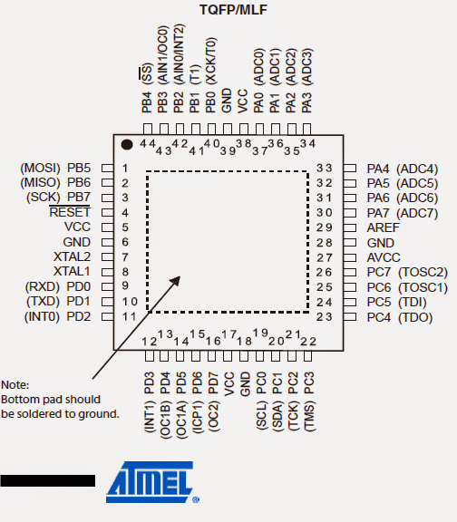
The Atmel AVR Atmega32 is a low power CMOS based microcontroller chip manufactured on the AVR advanced RISC architecture. It is featured for carrying out technologically powerful instructions within each of its clock cycles. The chip is also equipped with the capability of achieving throughputs rated at 1MIPS per MHz enabling the system manager to enforce […]

Filed Under: Arduino Projects Tagged With: ATmega32, Explained, Pinouts

Raspberry Pi Explained

Last Updated on December 5, 2024 by Swagatam 2 Comments

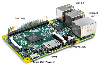
In this article I have explained about Raspberry Pi single board computer, their specifications, how to use them in a project, we are also going to do a small comparison between Arduino and Raspberry Pi, so that we can choose which of them are best for your projects. What is Raspberry Pi? Raspberry Pi is […]

Filed Under: Arduino Projects Tagged With: Explained, Raspberry

  • « Go to Previous Page
  • Page 1
  • Interim pages omitted …
  • Page 4
  • Page 5
  • Page 6
  • Page 7
  • Page 8
  • Interim pages omitted …
  • Page 16
  • Go to Next Page »

Primary Sidebar

circuit simulator image

Subscribe to get New Circuits in your Email

Categories

  • Arduino Projects (96)
  • Audio and Amplifier Projects (133)
  • Automation Projects (18)
  • Automobile Electronics (103)
  • Battery Charger Circuits (87)
  • Datasheets and Components (109)
  • Electronics Theory (149)
  • Energy from Magnets (27)
  • Games and Sports Projects (11)
  • Grid and 3-Phase (20)
  • Health related Projects (27)
  • Home Electrical Circuits (13)
  • Indicator Circuits (16)
  • Inverter Circuits (96)
  • Lamps and Lights (159)
  • Meters and Testers (72)
  • Mini Projects (28)
  • Motor Controller (68)
  • Oscillator Circuits (28)
  • Pets and Pests (15)
  • Power Supply Circuits (91)
  • Remote Control Circuits (50)
  • Renewable Energy (12)
  • Security and Alarm (64)
  • Sensors and Detectors (106)
  • SMPS and Converters (35)
  • Solar Controller Circuits (60)
  • Temperature Controllers (43)
  • Timer and Delay Relay (50)
  • Voltage Control and Protection (43)
  • Water Controller (37)
  • Wireless Circuits (31)

Other Links

  • Privacy Policy
  • Cookie Policy
  • Disclaimer
  • Copyright
  • Videos
  • Sitemap

People also Search

555 Circuits | 741 Circuits | LM324 Circuits | LM338 Circuits | 4017 Circuits | Ultrasonic Projects | SMPS Projects | Christmas Projects | MOSFETs | Radio Circuits | Laser Circuits | PIR Projects |

Social Profiles

  • Twitter
  • YouTube
  • Instagram
  • Pinterest
  • My Facebook-Page
  • Stack Exchange
  • Linkedin

Recent Comments

  • Swagatam on Convert any H-Bridge Inverter to Sine Wave H-bridge Inverter
  • Swagatam on 3-Step Automatic Fast Battery Charger/Controller Circuit
  • Swagatam on 3-Step Automatic Fast Battery Charger/Controller Circuit
  • Swagatam on Contact
  • Hậu on Convert any H-Bridge Inverter to Sine Wave H-bridge Inverter

© 2026 · Swagatam Innovations