In this post I have explained how to trick an inverter's "no load auto-shutdown" feature through an external circuit so that the inverter may be kept running even with minor, below permissible loads at the output. The idea was requested by Mr. Em.
Technical Specifications
Thanks for your prompt responses and guidance.
I was wondering If you could enlighten me regarding a peculiar problem related to No Load/Low Load Auto Shutdown phenomenon of UPS Circuits.
I have two UPS'es that are rated for 360 Watts. Unfortunately both have a load sensing mechanism thanks to similar micro controller circuit.
The battery back up time is fine if load is greater than at least 60-80 Watts. However, I only tend to use a humble 10 watt power WiFi Router with the UPS.
This tiny load is considered insignificant and ignored by the UPS circuit during power cut and it initializes a no load auto shut countdown of 300 seconds (5 Minutes). After the auto shutdown I can again restart the UPS, it beeps a little and gives another extension of 5 minutes .. and so on..
Collectively it can give back up of at least an hour, except for the 5 minute interrupt sequence which causes inconvenience.
Can I trick the circuit somehow to extend the time during no load ? I read in an "Ancient book" that No-Load Auto Shutdown could be disabled by biting off a resistor in the load sensing circuit of UPS. I have no idea which resistor could it be ..
Pardon me for the multiple shots,
I tried to give a better view..
Solving the Circuit Request
Thanks Em, yes you can trick it through an external circuit arrangement, because trying to modify the internal circuitry could be risky, unless you are absolutely sure about the proceedings.
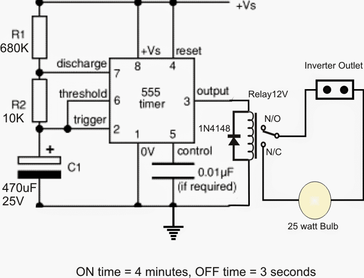
you can make a 4 minute 555 IC relay timer circuit with a 2 second ON time and 4.8 minute off time. and connect a 25 watt bulb load at its output relay via the UPS AC...
so this timer will switch ON for a second or two and connect the load to the UPS, forcing the UPS to extend and reset the output switch ON timing every after 4 minutes for the next 5 minutes.
I hope this might help.
Feedback
Hi Swagatam,
Thanks for the guidance, it worked..
I followed the second half of your suggestion about using a 25 watt load and it served my purpose to a significant extent. I connected a 25 Watt Bulb to the UPS, now it gives a run time of almost one hour and 10 minutes,
Have been using cum testing it for the past 10 days..and feel highly pleased..despite it being little inefficient.
Now coming back to the 555 timer, I found the IC on ebay, How do I program the timer for 2 second ON and 4.8 Minutes off ??
Any special equipment needed ?
Adjusting the IC 555 Output
Im glad it worked Em! for adjusting the 555 circuit you can take the help of any "online 555 calculator" and set the values of R1, R2 and the C of your circuit accordingly by matching the results presented by the software, through some trial and error.
There's another similar but more efficient method that can be tried using an IC 555 astable and a triac, as shown below:
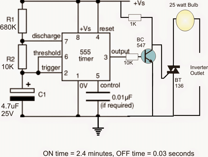
The above circuit will rapidly switch ON and OFF the load (25 watt bulb) at the indicated rate (2.4 seconds OFF, 0.03 seconds ON) keeping the load just dimly lit, and also tricking the inverter to "think" that the inverter is loaded, preventing the auto shut down.
Adding a Capacitor
One of the readers commented, saying why not add an appropriately rated capacitor across the output of the inveter, so that it will trick the inverter simulating it as a small load.
The idea looks simple, smart and effective,
So, instead of going through all the complex designs explained in the above sections, you can simply try adding a high value capacitor such as a 1uF/400V across the inverter transformer output, and solve the no load inverter shut down problem within minutes.


Comments
I have a 2500 watt (230V to 120V 50Hz) stepdown transformer. I use it for a (mechanical) toaster oven.
1. The transformer makes a noticeable noise on startup. Looking for a circuit to reduce the inrush current, start at best part of AC cycle, soft start.
2. The transformer has an idle power draw of 20 watts. Looking for a circuit to sense that the load is turned on, and enable the transformer. Sense if the load is off and disable the transformer. Optionally, delay the switch off for a few minutes. (If the load is turned back on, reset the timer, so it remains on.)
My toaster oven has a light, so it draws some power when switched on. But consider the case where the light is burned out. Then it needs the delay, or it will cycle too often — every time the thermostat switches on/off.
1) I think the surge issue can be solved by switching ON the transformer through a zero crossing circuit as shown in the second last diagram from the following article:
https://www.homemade-circuits.com/how-to-make-zero-crossing-detector/
2) This can be simply done by using a DPDT switch, so that the switch can be used to operate the load and the transformer simultaneously.
Hello Devendra, You can read the basic working details of UPS in the following article:
https://www.homemade-circuits.com/making-ups-tutorial/
UPS is an elaborate subject, and you will have to study all the stages thoroughly to be able to troubleshoot its fault. It cannot be explained quickly through a comment reply.
How to connect capacitor?
Hi… Please can i trick this problem by connecting capacitor on ac layout current?! I have the same problem and I'm trying to get simple idea.. Thanks indeed
With a common mans knowledge.. i ddnt understand anything on 555 ic or relay… but one thing which i understood is.. ups needs a higher voltage output…
I had three pin adaptor… i plugged it in and then i connected my table fan to it and also in the same adaptor i connected my modem… and it worked…
Not sure how long it can run.. by i used for around 30 minutes and then luckily the.power is back… so worth giving a try..
All u need is
1. A three pin adaptor where you can plug in multiple devices in it..
2. Table fan.. or anything which uses high voltage where mr. Ups is happy to supply power..
3. Connect or plugin your low power device. (Modem, mobile charger) to the same three pin adaptor.
Done… enjoy..
Hi, yes I think that could be tried, let us know if that really works, would be a great and a simple idea!
That seems to work erratically.
Tried 1uF/275V for a 360Watt UPS, which failed after approximately 2x the quick shutdown time; it could not keep tricking the UPS much longer.
Also tried 1.2uF/400V with a 720Watt UPS which failed the same.
If the UPS is unable to sense the capacitor as a genuine load then probably it will respond erratically. A 1uF capacitor will create a load of 50 mA x 220V = 11 watts, may be that’s not being recognized as a legitimate load by the system.
hi Swagat,i tried to construct a power resumption alarm circuit which i downloaded from a site,yet the buzzer keeps on beeping without shutting down.please can you help me with any power resumption circuit that can beep for 30 seconds and cut-off whenever power resumes
Hi Charles, please comment under the same article to which you are referring to, that will help me to view the diagram and then answer you correctly….
hi swagatam , i have same problem with my numeric ups ,in low loads ,it automatically turns off …but my ups turns off in under 30 seconds ….so could u tell me how to modify the relay .. ON TIME 1s and OFF TIME like 28s,
i tried online 555 calculator .. but cant understand anything since it asks so many variables like , astable ,monostable,frequeny,period,hig,low,n all and i only know two things …is the on time and off time ..ie 1,28 ,help plz
Hi Deepesh,
normally a 555 online calculator will ask for only three variables, R1, R2, and C1….
you can put any arbitrarily selected values for the variables and then go on experimenting with the R1/R2 values until the required ON time/OFF time….or Time High/ Time low values are evaluated.
the first link that you get in the search results is recommended and would include the above features.
yes 1 sec ON, and 28 second off looks to be the correct approach as per your specs.
Google the following keyword:
555 Astable Circuit Calculator