This small LM339 based solar battery charger setup is designed to optimize the charging of your battery using any solar panel while protecting it from accidental overloads.
Considering the extended battery life it allows you to achieve, it is an investment that quickly pays for itself.
Circuit Description
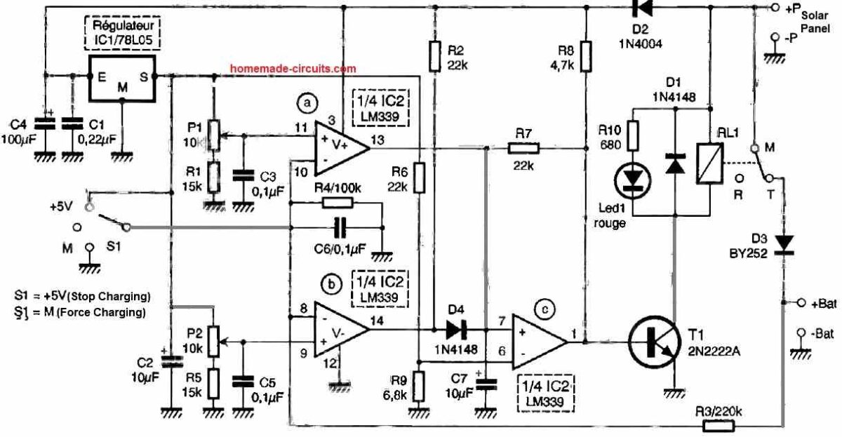
Our setup is nothing more than a dual comparator that connects the panel to the battery when the voltage at the terminals of the battery is too low and disconnects it as soon as it exceeds a certain threshold.
Since it operates solely based on battery voltage measurement, it is particularly suited for lead-acid batteries with liquid or gel electrolytes, which adapt well to this approach.
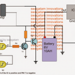
The battery voltage is divided by R3 and R4 before being applied to the inputs of the two comparators, IC2a and IC2b.
When it is below the threshold set by P2, the output of IC2b goes high, which also causes the output of IC2c to go high.
T1 is activated, and relay RL1 is energized, allowing the solar panel to power the battery and recharge it through D3.
When the voltage at the battery terminals exceeds the threshold set by P1, the output of IC1a goes low, which triggers the same response in IC1c and results in the relay being de-energized, preventing any overcharging of the battery.
To ensure that the thresholds set by P1 and P2 remain stable, they are powered through the integrated regulator IC1, carefully isolated from the voltage coming from the solar panel via D2 and C4.
This is because, during the relay switching, this voltage fluctuates significantly, which could affect the operation of the comparators.
A switch is also provided to allow manual control of the setup by forcing the voltage on the inputs of IC2a and IC2b to either high or low levels.
This allows for the interruption or, conversely, the forced charging when needed. For automatic operation, this switch obviously remains in the middle position.
Also Read: High Efficiency Solar Battery Charger circuit
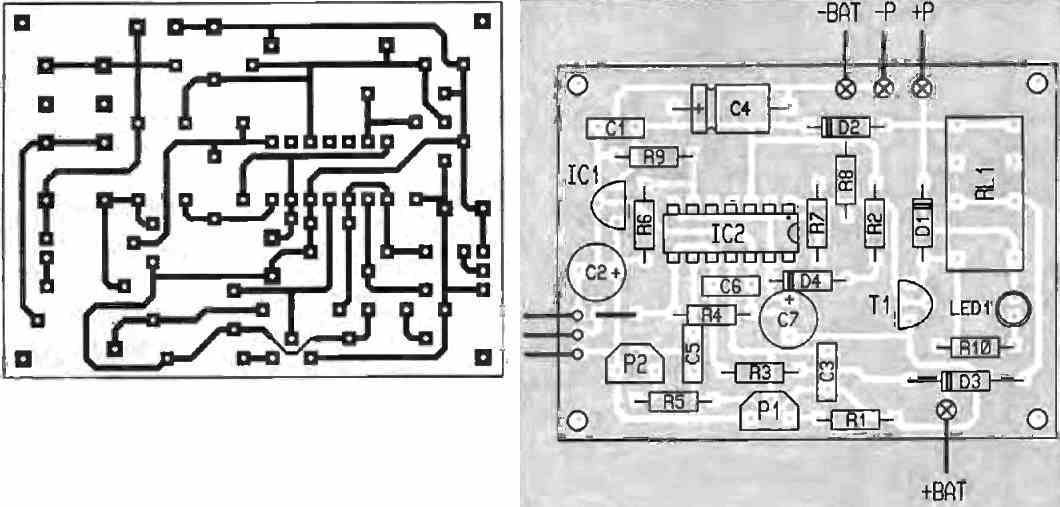
Construction
The printed circuit board that we offer supports all the components of the setup, and the components themselves are easily available as they are standard.
With the specified element values, the maximum charging current that the setup can handle is 2.5 A, which is well beyond the capabilities of typical solar panels available today.
However, if you wanted to go beyond that, it would be sufficient to replace RL1 with a model capable of handling higher currents and make the necessary adjustments with D3.
For proper adjustments and considering that the setup will likely spend a significant amount of time outdoors, it is recommended to use CERMET potentiometers for P1 and P2 instead of carbon models.
The wiring presents no difficulties and should be done in the standard order of passive components followed by active components, ensuring the correct orientation of polarized components (diodes, transistors, capacitors).
How to Adjust the Presets
The operation is immediate but requires adjusting P1 and P2, which can be easily done with a simple stabilized power supply.
To do this, short-circuit the +BAT and +P points and power the setup between -P and +P using your stabilized power supply.
Set S to the middle position and adjust P1 and P2 so that the relay switches off when the voltage from your power supply is around 14.5V and switches on when it is around 13V.
If the setup is to be used outdoors, it should be placed in a protective enclosure to shield it from moisture.
Also, avoid exposing it to direct sunlight, as excessive heating could alter the switching thresholds determined by P1 and P2.
By following these two usage precautions, you can ensure many years of reliable and loyal service.
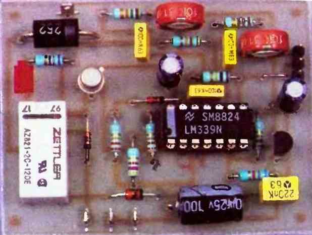
Prototype Image

Comments
Hi sir, how are you doing sir,
Sir I have a 300w solar panel with 32.7v 9.2A rated, but the issue is that the panel is not generating more than 2.5A, by the way I ran my test on the panel itself not from inside the house and my battery is very low, what to do here sir?
Hi Tunji,
How did you check the solar panel short-circuit current?
You must expose the solar panel to day’s peak sunlight and without any load across its output wires, you must connect an appropriately rated DC ammeter directly across the solar panel wires and check the instantaneous current reading.
Let me know if you did the same…
Thank you for quick response sir, I actually use the mppt with battery as load on it directly on panel, to take the readings sir.
The correct way is to take the reading without any load, under peak sunshine, only then you can verify the actual performance of the solar panel.
Thank you sir, I later discovered that my wiring is the issue, after changing them, I was able to get the exact amps and power needed.
No problem Tunji, glad the problem is solved now!
This is an interesting design i discovered when exploring options. In my case I am looking for a limiter circuit that safely protects against too high of DC voltage on a large solar panel array of 5720 Watts Rated at 16.81 Amps and at cold temperatures during winter may slightly exceed 450vdc to around 452vdc and I need it to limit it to 450vdc WITHOUT cutting off the solar output, but rather burn off the excess voltage or do some sort of step down in voltage and step up in current in an overvoltage event only as a short term workaround, e.g. hours not weeks. I want this circuit to go in front of the solar charge controller / MPPT device. So it would need to not interferre with power point tracking during normal operation. I suppose during a bleed-off over voltage mode, it wouldn’t much matter. Thoughts?
James Tialiden-hello-from-attampt22@gmail.com-feedback me directly-Igor Moscow Russia. Thoughts are these:
0-name all panels as you like – 1st, 2nd, 3rd, 4th, e.t.c. (or A, B, C, D, E, e.t.c. or else) forlife with no change of these names. Write down with a reliable inks/engrave/similar these names on each panel.
1-Your array of solar panels is the – subsequently as one cirquit are19 panels by 18volt per panel each 16.81ampere – yes or not? These panels shell be everyone size 2×1 meter (not more than 20% less of these) of total square – with frame/fixtures? If both “yes” – you should place 18 diodes (more than 25 amperes not less than 350volt everyone) after each one panel to be the: panel1-diode-panel2-do=diode-panel3-diode-panel4-diode-…panel19 for prevent of voltage reverse damage with case of fire of panel at particular shaded of anyone panel.
2-depends on local conditions – if some of panels are often in a shadow in compare with other panels – shadowed panels is better to separate to “2nd group” to be connected to a 2nd independent controller – both controllers are work to same one load as an independent sources of power. Is it good or not – depends on %% of shadowed time and on effeciency rate of controllers and on some others-linked with the loads – needs exact measures and money counts of the equipment.
Thank you for your kind feedback, and glad you found the post helpful.
Actually the above design looks an overkill, because the same operation can be done with just a single op-amp.
Nevertheless, yes the design can be used for your specified application.
This can be placed in between the solar panel and the MPPT.
The N/O contacts of the relay (indicated as R) could be wired with some other suitable circuit to step-down the excess voltage and convert it into an equivalent current.
Let me know if it makes sense…
Thank you kindly for the prompt response. As I am not an EE, an a novice at circuits, do you have a recommendation or link to a more suitable design (such as the op-amp you mention) for my needs, or what components in the above diagram would need swapped out, e.g. bypass diode values, etc? I’m hopeful I can find a link to a diagram I can follow for my purposes. I don’t understand why this type of device is not frequently offered for those with large solar arrays as an inline over voltage protection device to protect high cost Solar Charge Controller / Inverter / MPPT systems. As this concern is nothing new, and disabling an entire array as opposed to keeping it operating under max voltage spec seems unpreferred for most of us that still want charging benefit.
Yes you are right, a simple over voltage cut-off must be employed by all large solar panel systems to ensure a safe charging configuration.
Ok, so you can try the following simplistic design to make sure your battery is never overcharged, while the N/C contact of the relay can be used to access the excess voltage from the solar panel for some other desired purpose, for example, by hooking up a buck converter with it, or may be for activating a water heater system.
https://www.homemade-circuits.com/wp-content/uploads/2024/08/solar-panel-optimizer-circuit.jpg
Let me know if you have any further doubts or questions….
I have a solar street light. After 1 year of use, its lifepo4 batteries were damaged.
1-Can I replace them with 18650 li-ion batteries connected in parallel?
2- how can I make a charging circuit board that provides protection and balance for the batteries?
3- Can I use the original circuit board as a power supply. And if so, does it keep the fuction of the remote control and the automatic darkness on/off function?
Thank you very much
Hi, here are the answers to your questions:
1) Yes you can replace your lifepo4 batteries with 18650 li-ion batteries, just make sure the voltage rating of the two are matched correctly.
2) I do not have a proper balance charger circuit with me right now, so can’t suggest much about this, it is better to buy a ready made unit instead.
3) You can use the original board as the power supply. If the original power supply was earlier working with the remote control and the darkness ON/OFF, then it should continue to work with the new batteries.