In this post I have explained about a simple yet sophisticated automatic emergency light circuit which can be considered "smart" due to the involved advanced features and an inexpensive design. The idea was requested by Mr. Lokesh.
Technical Specifications
Hi sir, I am so glad to see your interest towards electronic circuits. So eagerly waiting for circuit which will be having following (few or all) feature.
- Low Battery Cut-off
- Overloading protection
- Short Circuit protection
- Reverse current protection
- Reverse polarity protection
- Thunder protection
- Over discharge protection
- Auto battery shut-off at Low voltage detection
- Overcharge protection
- Auto charge stop/ High Volt Detection
- Battery capacity level display(SOC)
Making this circuit for underprivileged location as donation for poor via charity So hope I can have one ckt diagram with some or all features mentioned above or lts link..
Looking for your reply ..
With full excitement
Thank you
Regards
Lokesh
As part of tribute to you sir
The Design
Amongst the many interesting features requested above only two are not included in the proposed smart LED emergency light circuit which are: 1) Battery Capacity level indicator, and 2) thunder protection.
The battery capacity level indicator is eliminated to keep things simple in the design, and the thunder protector feature is not considered in the circuit since it may be included in the form of an external attachment and cannot be a part of the electronic circuit.
Apart from the above all the remaining features are included in the design making it a truly impressive and a smart.
So I have explained the simple yet advanced design in detail with the help of the following description:
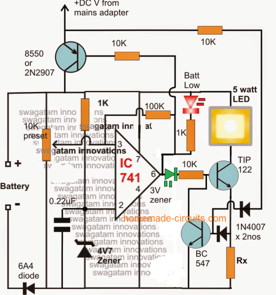
Referring to the above shown smart automatic emergency light circuit, the IC 741 forms the battery level detector and the cut off stage.
How it Works
The 10k preset is adjusted such that the output of the IC goes just positive whenever the "full battery" is reached at the selected level
This is indicated by the illumination of the green LED and the shutting off of the red LED. When this is detected the IC goes into a latching mode due to the presence of the 100k feedback resistor.
Since this 100k resistor also forms the hysteresis control and becomes responsible of restoring the charging process at the desired low battery level, it must be so selected that it executes this low charge restoration process at the correct preferred low battery level.
During the absence of mains power, when the low level is detected by the opamp, the TIP122 is instantly switched OFF to prevent over discharging of the battery.
The transistor TIP122 becomes the LED driver device, which triggers ON into a standby mode as soon as the battery gets fully charged, and switches ON the LED in case the mains power fails.
Calculating the Current Limiter
The associated BC547 transistor ensures a safe, restricted current to the LED as set by the value of the resistor Rx.
Rx is calculated with the help of the following formula:
Rx = 1.2 / LED max safe current (in amps)
The PNP transistor on top is positioned to supply the charging voltage for the battery. It is enabled in the switch ON position whenever the battery voltage is detected to be below the lower threshold and while the opamp output is rendered negative or low, on the other hand this PNP transistor is instantly switched OFF when the battery is detected to be fully charged and the opamp output toggled to a high or a positive potential.
The supply voltage at the collector of this transistor may be derived from any standard SMPS AC/DC adapter unit.
The feed back link from the collector of the PNP transistor to the base of the BC547 takes care of the emergency LED changeover action, which ensures an immediate, automatic switch ON of the LED whenever the grid voltage fails and vice versa.
If you have any further questions regarding the design, you may feel free to use the comment box below to jot in your valuable feed backs.


Questions & Answers
super,super,tank you.you the best
My pleasure Gogotu…
What DC voltage range it can handle?
it's between 5v and 15V
Thanks a lot sir. . Got it as expected. .. 🙂
if possible may I get Component list separately. .
lil blur over there so m asking sir hope you don't mind. .
and also let me know Whether it's possible to add an inverter CKT of 50watt to run Light load like Cfl n charger. .
Thank you
Lokesh, just click on the diagram to enlarge it, all the parts will be clearly visible….and all are standard components, with resistors rated at 1/4 watt
if you type "50 watt inverter" in the search box, you will find the required one immediately.
Hi Bro,
Nice project.I want small changes in your project.
a) I want to use three 1 watt leds in parallel in place of 5 watt led.
b) Battery is 3 cell nimh pack 2500mAH.
c) Charging source 5v adaptor 500mAH.
Can i use these to my lamp?
Can i use 3.3v zener in place of 3v zener?
Please give reply soon.
Thank you.
Thanks,
You can use it with minor changes, please let me know what's the voltage rating of the NiMh cells, so that I can specify the alterations
Battery normal voltage is 3.6v,when fully charged it gives 4.4v at 2500mAH. till now I'm using it to connect directly to 3 1watt leds in parallel with individual 10 ohms resisters. this setup gives me 4hrs backup max. I wanted to make it automatic as mentioned in your above project.
Thank you.
Surya, then you can use it without any change in the circuit except Rx, which can be calculated as per the given formula.
Hi Mr Swagatam,
I've got the idea, please bare with me, because i'm new to circuits design. i actually thought about using opams to create the circuit that i need, so that makes me feel better i was heading in the right direction. however, how can i update the circuit to operates on 26-30 volts and 3 amps. I'll be using a dc to dc voltage booster and steady current between the battery and this circuit, as the battery wont be able to supply the required voltage. so, im not sure if this circuit will still remain to operates with the voltage booster between the battery and the circuit. also, i will have another voltage booster to be connected the main power adapter as the adapter will only produce 19v and i need 26-30 volts. im kinda lost with this part because i need circuit to:
1) as soon as i connect the external power automatically it will disconnect the battery and supply the system, in the mean while charging the battery.
2) overcharging protection( which included in the above design).
3) battery low and full charging indicates ( which included in the above design).
4) also i don't know what is the formula to help how to determine the voltage required across my battery to charge it with( battery will be extracted of old laptops.total will be 22V with 6 apms at no load)
5) also, i don,t know the formula to indicate how long my battery will last, and how to calculate the time if i want a battery to last me two hours.
I'm sorry for those many questions, but i'm trying to get help and improve my skills in designing as i'm very new to electronics world.
thank you very much.
sincerely,
Mamdouh.
Hi Mamdouh,
boost converters are not easy circuits, and making two them will make the design unnecessarily complex and inefficient, so I won't recommend this idea.
You can use a two 12V batts in series to achieve the 26V, and use a 26V adapter for the charging purpose, that will be much easier to configure.
If possible I'll try to update the design as a new circuit using two opamps as requested by you soon
great, thanks for help.
to give you a full perspective of the hole project. it's pretty much the same idea represented above.
however, my led will be 100 watts consuming so it needs a steady power with current limited to 3 amps max.
i will be added a heat sink with fan( a cpu heat sink with it's fan) to keep my led and component temperature under control.
so it will:
1) switch to turn the system on and off.
2) off course my battery to supply the system in absent of external power and charging while external power is connected in the mean while supply the system.
3) the whole safety thing for the battery.
thank you very much.
OK, noted, will try to publish it soon
sure, just let me know when you publish it. and i really appreciated.
thanks a million.
I'll try to remind you after the posting it… if I forget please check back with a reminder…
OK, I will include all these…
hi Mr. Swagatam,
just a reminder, if you have posted the circuit let me know please and thank you.
Hi Mr. Mamdouh,
I have published it here:
https://www.homemade-circuits.com/2016/05/opamp-low-high-battery-charger.html
thank you! good question…the negative should be connected to the line which is connected with pin#4,
May i use 12v 7.2Ah battery and 12v 10W led with this
yes you can!
..replace TIP122 with TIP142
Hi Swa,
If i want to equipe this with dark activated feature, can i just put a LDR in parallel to the collector and emitter (ground) of the BC 547.
Thanks
Kanta
Hi Kanta, no that won't do.
Instead you could connect the LDR across the base of BC547 and the positive supply rail.
And also make sure to connect a 10K resistor across base/emitter of the BC547
hi sir. can i use 12volt 7.2 Ah battery in parallel for this circuit to run 5 of 12Volt ,12W LED or do i want make any changes in this circuit
Hi aariz, you can replace TIP122 with TIP142 and then proceed, however 12V 1.2AH will not be able to sustain a 5nos 12a watt LEd for more than 1/2 hour
Hi sir if i use 12volt 7AH battery to connect 5nos 12 watt led,how many hour it will work? Do u have any method to calculte the time.
that can be difficult to judge, you may have to try it practically and check
you can also take the help of this software
https://www.homemade-circuits.com/p/battery-calculator.html
No, it won't
Hi Swa,
Could you please explain why the Rx formula is using 1.2 ?
Thanks
Kamta
Hi Kanta, it's to compensate the 0.6V drop involved by the BC547 and an additional 0.6V drop by its base diode
Hi Swa,
I have 6V 5AH battery for this project. What is the correct DC Voltage from the main adaptor ?
Can i just use 6V 1Amp transformer and bright rectifier without any regulator?
Thanks
Kanta
Hi Kanta,
yes a 6V 1 amp trafo and bridge will do, make sure to use a high value filter capacitor and switch OFF the charger as soon as the battery terminal voltage reaches around 7.1V
Hi Swa,
Thanks for the prompt response. What is the minimum value of the capacitor, since the higher value, the bigger phisical size of the capacitor is.
Thanks
Kanta
Hi Kanta, You can try a 2200uF/16V capacitor, this will be quite good
Hi Swa,
If i am using 6V battery, how do i do the setting on the 10K preset ?
Thanks
Kanta
Hi Kanta, I have explained it in the following article elaborately
https://www.homemade-circuits.com/2016/05/how-to-set-ic741-battery-charger.html
Hi Swa,
I have several questions:
1. With the 100K resistor as hysteresis control, what is the low level voltage for 6V battery to trigger the charging process. If the main power fail, what is the lowest voltage level for the battery will be to prevent it over discharging with this 100 K resistor?
2. If the opamp IC is also controlling the over discharging and at the same time also control the over-charging to the battery, the TIP 127 will only conducting when the battery reach the desired high level voltage, hence, if the battery voltage slightly drop, the TIP 127 will be shutting off eventhough the battery voltage is still higher than the desired lowest voltage level? Let say the cut off fully charged battery for 6V battery is 7.1V, when the battery below 7.1V, the opamp IC will go down and 0 Volt come out from zener of pin #6 and it will shut down the TIP 127 eventhough the battery is still more than 6V?
3. The diode (6A10) is preventing the ninus (-) battery going to the opamp IC and the whole system. Could you please explain where the system will get the minus (-) battery in the event the main power fails.
I have bought all the materials to construct this emergency LED for 3 units. Awaiting your support soon. Thanks
Kanta
Hi Kanta:
1) You will need to find it by measuring the voltage at pin#3 for confirming the correct value of this resistor such that the discharging stops and charging initiates at the specified lower threshold voltage.
The value should adjusted such that voltage the pin#3 just becomes lower than pin#2 at this lower threshold level. For this you can replacing the 100K with a 220K preset and with a 1K series resistor.
2) The feedback resistor is introduced so that the charging stops at the 7.1V and initiates only at 5.5V
3) the minus pole works in the opposite direction to the (+)
In point 2) did you mean to say that once recharging is initiated and the battery has charged to some point which is lower than the full charge level but higher than under-charge level, and during this time if the mains switches OFF, then the opamp will continue to keep the LED OFF….right?
yes that's right this will happen unless some method is employed to rectify this. I'll try to upadte it soon.
…I think adding a diode in series with the 100K will solve the issue,,,,cathode towards pin#3 and anode to 100K
Hi Swa,
I have tried the simultion by using variable power supply on the battery terminal. When the 7.1V, i set the 10K to the position that the green led illuminated, i fixed the preset position. I adjust the variable PSU (the pretending battery) to 6.8V then the led went off, the TIP 127 was off
Could you please help how to set to have 5.5V to initiate automatic charging?
Thanks
Kanta
Kanta, simulation will not help, you will have to build it practically and then set the parameters using a digital multimeter, that's the right way to go!!
By the way where's TI127 in the above design, are you referring to TIP122??
Hi Swa,
As for the diode of 6A10, you are right, my mistake which over looked the diode lead. However, if the main DC is connected to the line on the pin #4, then how the battery will be getting charge?
Thanks
Kanta
…main DC (-) should be connected with the battery (-), and not with pin#4 line.
6V4 is specifically for safeguarding the LED and the IC from a possible reverse battery polarity connection
Hi Swa,
What i meant i have constructed the system in the PCB, however for setting the cut off and over discharge protection correctly we need to do it with the variable PSU to do the setting on high and low threshold. So, when i lower down the PSU to 6.9V, the TIP 122 became off. This is what i meant. Please help me how to set it to have the threshold to 5.5V.
As for the main DC minus (-) connetion to pin#4, i am referring to your answer to one of the readers in the above comments. So, what is the correct way to connect the minus main DC minus (-), to battery minus (-) or to pin #4 of the IC ?
Thanks
Kanta
OK, first I would suggets you to connect two LEDs with series 1k resistor across the pin6 and the (+)(-) rails, I am sure you know how to do it.
initially keep the 100k disconnected and now set the 10k preset for the full-charge threshold cut off…this should illuminate the lower LED and shut off the upper LED….and also the 2N2907 or the 8550…and swtch ON the TIP122.
seal the preset now with any glue.
now replace the 100k feedback resistor with a 100K preset, connect it across pin6 and pin3 with a series 1N4148 diode.
keep the 100k to minimum level that this zero resistance, and connect it across the pin6 and pin3 (with a series 1N4148 diode, can be on side of the preset)
now reduce the voltage to the lower threshold, and slowly adjust the 100k preset until the output of the opamp reverts to zero, switching OFF TIP122 and switching ON 2N2907)
lower LED will be OFF, and upper LED will be ON now
correction required in the first sentence, the 100k feedback should have a 1N4148 diode in series not a 1K