In this post I have explained about a simple yet sophisticated automatic emergency light circuit which can be considered "smart" due to the involved advanced features and an inexpensive design. The idea was requested by Mr. Lokesh.
Technical Specifications
Hi sir, I am so glad to see your interest towards electronic circuits. So eagerly waiting for circuit which will be having following (few or all) feature.
- Low Battery Cut-off
- Overloading protection
- Short Circuit protection
- Reverse current protection
- Reverse polarity protection
- Thunder protection
- Over discharge protection
- Auto battery shut-off at Low voltage detection
- Overcharge protection
- Auto charge stop/ High Volt Detection
- Battery capacity level display(SOC)
Making this circuit for underprivileged location as donation for poor via charity So hope I can have one ckt diagram with some or all features mentioned above or lts link..
Looking for your reply ..
With full excitement
Thank you
Regards
Lokesh
If successful I am in plan to put ur & website name on my device 🙂
As part of tribute to you sir
The Design
Amongst the many interesting features requested above only two are not included in the proposed smart LED emergency light circuit which are: 1) Battery Capacity level indicator, and 2) thunder protection.
The battery capacity level indicator is eliminated to keep things simple in the design, and the thunder protector feature is not considered in the circuit since it may be included in the form of an external attachment and cannot be a part of the electronic circuit.
Apart from the above all the remaining features are included in the design making it a truly impressive and a smart.
So I have explained the simple yet advanced design in detail with the help of the following description:
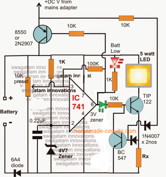
Referring to the above shown smart automatic emergency light circuit, the IC 741 forms the battery level detector and the cut off stage.
How it Works
The 10k preset is adjusted such that the output of the IC goes just positive whenever the "full battery" is reached at the selected level
This is indicated by the illumination of the green LED and the shutting off of the red LED. When this is detected the IC goes into a latching mode due to the presence of the 100k feedback resistor.
Since this 100k resistor also forms the hysteresis control and becomes responsible of restoring the charging process at the desired low battery level, it must be so selected that it executes this low charge restoration process at the correct preferred low battery level.
During the absence of mains power, when the low level is detected by the opamp, the TIP122 is instantly switched OFF to prevent over discharging of the battery.
The transistor TIP122 becomes the LED driver device, which triggers ON into a standby mode as soon as the battery gets fully charged, and switches ON the LED in case the mains power fails.
Calculating the Current Limiter
The associated BC547 transistor ensures a safe, restricted current to the LED as set by the value of the resistor Rx.
Rx is calculated with the help of the following formula:
Rx = 1.2 / LED max safe current (in amps)
The PNP transistor on top is positioned to supply the charging voltage for the battery. It is enabled in the switch ON position whenever the battery voltage is detected to be below the lower threshold and while the opamp output is rendered negative or low, on the other hand this PNP transistor is instantly switched OFF when the battery is detected to be fully charged and the opamp output toggled to a high or a positive potential.
The supply voltage at the collector of this transistor may be derived from any standard SMPS AC/DC adapter unit.
The feed back link from the collector of the PNP transistor to the base of the BC547 takes care of the emergency LED changeover action, which ensures an immediate, automatic switch ON of the LED whenever the grid voltage fails and vice versa.
If you have any further questions regarding the design, you may feel free to use the comment box below to jot in your valuable feed backs.


Comments
hi sir can you provide a circuit for smart led emergency light which turns on only when power line goes off.
led does not depends by on/off button
Hi Fayyaz, the above circuit will do exactly that. It does not depend on ON/OFF switch.
hi sir can u provide some circuit for automatic contact less panipuri water filling machine ,with adjustable time and manual operation also possible
Hi Harvinder, yes a circuit can be designed to open and close a tap that will fill puris without contact.
Sir
Where is the negative cable from adapter source and where is it attached and, 3 volt zener dioda, and i don’t find the symbol there, thank a lot
Rudi, the battery (-) is the negative point for the adapter also…
Mr. Swagatam, I would be glad if you send me a circuit board with PCB drawings and over-discharge, and over-discharge, with automatic discharge. Vith 12 v.8-10 Amp. Thanks in advance. I wish you a good day
Hello Mr. Mehmet, you can try the designs explained in the following article:
https://www.homemade-circuits.com/opamp-low-high-battery-charger/
But I do not have the PCB designs for them, you will have to contact a PCB designer for this.
Hi swagtam, please lookinto the undernoted circuit.
https://drive.google.com/file/d/1Ng9tC3sbhwrI1FfDFz3_xXsLNYDoFOto/view?usp=sharing
here i use two comparator, one for high voltage U1 and another for low voltage U2 monitor. Now i want to add both these two for charging the battery when the battery level down near certain voltage like 9volt and the Emergency light connect to battery will not light up for further over-discharge. Again when the battery level up above 12.5 volt the charging should. Please help me to add some PNP-NPN circuit to make it complete.
Thank You.
Hi chandrashekhar, I already have similar circuits in my website, , you can find it here:
Op amp Battery Charger Circuit with Auto Cut Off
Also the smart emergency lamp explained in the above article uses a single op amp and does both the operations of overcharge cut off and low discharge cut off.
Hi Swagtam, I want to charge my 3P LION battery of 1200mAh each with power adapter of 12V 500mA. And my emergency led are connected with 3s 4P (means 240mA total-2835 SMD-02W,3V).
1. Now my question is how to IC will determine how much battery voltage will be signalled “battery Low”. Understand that 10K preset will determine battery charge voltage.
2. Can I use LM358 IC instead of 741 ?
3. As per your calculation the Rx should be 1.2/0.024= 5 Ohm 2.88 Watt. Am I correct.?
4. Can I modified to 1K from 10K which connected to TIP 122?
5. What is use of 4v7 zener. Is it determine the battery low signal? Then in my case 7.5volt (2.5*3series battery). Am I correct?
Please respond to my above queries..
God Bless You.
Hi CHANDRA SEKHAR,
3P refers to 3 batteries in parallel? but in your 5th point you have said that the batteries are in series, please clarify how is the battery configured, then I will try to help? Also please mention the battery Ah spec of each Li-ion that you have used.
Hi Swagtam, sorry for typo. actually my lion battery are in series. 3S. All are 1200 mAh each.
Awaiting for early reply
Thanks Chandrashekhar, I’ll try to solve it for you:
1) yes you can use LM358 op amp
2 For 1200 mAh, a good charging rate would be at 500 mA, so Rx = 1.2 / .5 = 2.4 ohms, and wattage of the resistor will be 0.6 watt or 1 watt
3) 1k can be used for TIP122 base, although it will depend on its collector load.
4) 4.7V is the reference level applied to the inverting input of the op amp, and it does not need any change for your battery.
Rx=1.2x LED MAX SAFE current
So in my case Rx=1.2x 0.240(each led 60mA of 4P led)
Hence Rx=0.288 ohm and 1.2watt
Am i correct
yes, it seems I mistakenly considered the battery charging current in my calculations instead of the LED.
if the LEDs are 60 x 4 = 240mA then the as per ohms law:
R = V/I = 1.2 / 0.24 = 5 ohms
wattage of the resistor will be 1.2 x 0.24 = 0.288 or a 1/2 watt will do.
My 1st questions was, how the system know what will be the low voltage of my battery. In my case my battery low voltage will b 2.5*3=7.5 volt. Then how to set this volt as low voltage? And what the use of 10k Pot?( Is it for over charge protection)
OK,it seems I overlooked it.
the low battery cut of is set by the resistor connected between pin6 and pin3. The value of this resistor should be such that it creates a voltage at pin3 slightly less than pin2, when the battery voltage is 7.5V.
So you must artificially operate the circuit with a 7.5V and try different resistors until you find the pin3 voltage just below pin2 voltage (4.7V)
…yes the preset 10k is for over charge cut off. Initially keep the preset at the zero level, apply the full charge voltage externally to the circuit, then slowly adjust the preset until the RED led just lights up and green shuts off..your circuit is set now for the full charge cut off
The secondary battery is in series with a diode. How can the circuit charge it?
The adapter negative must be connected with the battery negative directly.
Hello, Mr. Swagatam, I have a question that is not about the circuit above, i hope i’m not disturbing you… I tried to construct a circuit taken from a book of electronics, available at the below link (please download the file fast, the link will expire):
https://www.homemade-circuits.com/wp-content/uploads/2019/07/transistor-clap-switch.png
The circuit has two parts: the first one, in left, is an circuit that makes a led to go on/of by vocal comand (by clapping hands) and to remain in this state until a new sound is detected. This circuit is all right, i constructed it with succes. The problem occured at the circuit în the right, that works în the next manner: when the led goes on, the light falls on the fototransistor Ft1, and by the meaning of the tyristor Ty1 (T1N6 is not longer available, i used the equivalent C106M) it should light up the bulb Bec 220V/60-100W maximum. But when i tried the circuit i made, it didn’t worked. It worked when i connected the zener diode DZ1 reverse ( with the anode at + and the cathode at – ), but not as describted above: the bulb lighted up when the led went of, not as espected. This wouldn’t be a problem, but the problem occurs when i tried to substitute the bulb with a radio with transformer, or with a Tv (this should work, as described în the book). În the case of the radio, it didn’t went off, and în the case of the Tv, the fuse Sig. rated 0.5A burned off. How to modify the circuit that could drive a radio, a Tv, etc? Could you give me a sugestion? Thank you!
Hi Mihai,
I have migrated the circuit inmy website so that it stays permanently.
The zener polarity is correct in the diagram, if you reverse it, it cannot work, because the power to the opto-coupler will be shorted by the zener. So the the zener polarity must be exactly as shown in the diagram.
You can connect an LED in series with the gate of the SCR, that will show exactly how your ScR is responding
Hello. I did your circuit and I’m planning to use 12.6v lithium ion battery. I tried the circuit with 15v adapter and 12v 5watts LED bulb. The bulb lightened up but it is so dim. I want to have a brighter output for the bulb. What can you suggest me to do?
Thank you very much! This project will determine my final grade.
Hello, the brightness will depend on the battery current and voltage. If battery power is low led brightness will be low. And while the adapter is connected the LED will remain shut off. Please note that the circuit should be implemented by understanding the stages correctly, otherwise you may find it difficult completing it. If You have further problems, please free free to ask me.
In the meantime please try reducing the base resistor of TIP122 to 1K, and see if that helps, and make sure the green LED is ON when the adapter is not linked with the circuit.
Oh I kinda misunderstood the circuit. So that’s how it works, thank you. Is it possible if I will put a switch? How?
I am glad you understood how it works! A switch can be added in series with the battery positive wire. For the adapter, you can put it in series with the positive wire of the adapter.
I want to use charger socket for my DC adapter. But I don’t know where to connect the positive, negative and ground? Can I have some help please?
Also, do I need to change anything if I am going to use 12v adapter and 8.4 li-ion battery?
Thanks.
you can cut the socket, and look for red and black wires from the adapter cable. then you can use a 7809 IC for dropping the 12V from these red/black wires to 9V. Finally this 9V could be used for charging your battery. But make sure to adjust the opamp to cut off at 8.4V otherwise the battery may get damaged.
1.What will be the adapter that I need to use if I will use 12v lead acid battery that are commonly use in motorcycles?
2. Do I need to change some components?
Sorry for the trouble. Thank you.
for a 12V battery, you can use a 14V adapter, with current rating 8 t 10 times less than the batter Ah rating, this can be achieved simply by using a 0-12V transformer and rectifying it with a bridge rectifier and filtering using a 2200uF/25V capacitor.
no changes would be required in the circuit, just remove the 100k resistor, it is not required
What value of diodes should I use?
the 6A4 diodes should be 2 times more than the current rating of the LED, rest can be as is
What mm is the LED indicator and the 5 watt LED light? Thank you!
the LED indicators could be any 5mm 20mA LEDs, the 5 watt LED is the emergency LED light, which could be as per your preference.
Hi! Is it okay if I will use 12v adapter, 9v rechargeable charger in this circuit? Thank you!
yes you can do it, no problems, because the circuit has all the required protections!
Hi again! What about the DC voltage for main adapter? If I will use 12v, 15 ah lithium ion battery?
Thank you! Your reply will be really appreciated.
For the power supply you will need a 14V 1 amp, adapter. You can eliminate the 100k feedback low sense resistor across the opamp pins, it is actually unnecessary.
Is 12v power supply will not work? Sorry I’m not really good at this.
for a 12V battery the charging voltage should be 14V optimally, 12V will not work
Hi! If I will follow the whole circuit with 5 watts LED bulb and 12v as the main supply, what kind and value of battery can I use? I’m not really good at this. Hope you understand. Thank you so much.
Hi, if your LED is rated at 12V, then the battery will need to be at least 12V, 15 Ah for getting a decent backup of around 5 to 6 hours.
also make sure to select Rx = 0.3 ohms, 2 watts
Hi, Am going to make a emergency light circuit with 4v, 3A battery (4v battery*3 Nos in parallel). Can I use the above same circuit or do I require any changes in the circuit with 6A4 diode and 4V7 Zener?
And regarding the regarding the LED current limiting calculation,
Rx = 1.2 / LED max safe current (in amps)
If I use 5mm LED means, the current will be 20mA (I.e. 0.02A).
So the calculation will be as 1.2/0.02= 60ohms.
If 10 LEDs means, 1.2/0.2= 6 ohms. Am I correct?
Hi, you can use the same circuit for any LED and battery specs only by replacing the current handling diode and the transistor.
In your case you can use a 2N2222 or 8050 transistor instead of TIP122, and use a 1N4007 diode in place of 6A4
Hi, How to limit the current for the battery charging? I will be using 4v, 2A battery which require 200mA charging current. But I will be using 12v, 1A SMPS adapter.
And can I use a 12v, 1A adapter for the above circuit to charge a 4v, 2A battery?
Hi, the following circuit will be most appropriate:
https://www.homemade-circuits.com/how-to-make-current-controlled-12-volt/
Adjust the pot or preset to get 5V at the output, and calculate Rc to give around 300mA output.
If you are using a Li-ion cell then a single 7805 IC will do the job for you
ok…thank for your help sir.
you can use 1 amp current, not more than that. It should be 14V / 1 amp