• Skip to main content
  • Skip to primary sidebar

Homemade Circuit Projects

Need circuit help? Post them in the comments! I've answered over 50,000!

Blog | Categories | About | Contact | Calculators-online
You are here: Home / Meters and Testers / Simple Transistor Diode Tester Meter Circuit

DIY Circuits | Learn Basics | Arduino Coding

Simple Transistor Diode Tester Meter Circuit

Last Updated on January 2, 2024 by Swagatam 4 Comments

In this post I have explained how to make a simple yet efficient transistor/diode tester circuit, that will not only test the quality of a BJT, but will also help to identify whether it is is an NPN or a PNP. The circuit was designed and contributed by Mr. Henry Bowman.

Circuit Operation

Referring to the transistor tester circuit diagram, when the 555 timer on the left puts out a positive pulse, it triggers the timer on the right to put out a negative pulse and vice-versa.

Meaning, when the output on pin 3 of the left side 555 goes high, the output pin 3 of the right 555 goes low. 

When the output pin 3 of the left side 555 goes low, the right side 555 pin 3 goes high.  The right side 555 output will always be opposite polarity from the left side 555 pulse.

It’s similar to a flip-flop circuit.  You have a positive and negative continuing reversal that is applied directly to the emitter and to the collector via the center tap of the transformer.

The first 555 sets the pulse rate to be about 1.5 seconds width in position 2. Some transistors testers require the use of a DPDT switch to reverse the polarity depending on NPN, or PNP type transistors.

My design eliminates the switch.  The base receives a portion of the collector voltage through VR2 and resistor R7. Oscillations will occur if the transistor is good and the appropriate led will light.

If the transistor is shorted, both led2 and led3 will light and oscillations will not occur.  To test a diode connect it across the E and C leads.  Place selector switch in position 1.  The polarity reversals occur much faster in position 1.  It doesn’t matter which way you connect the diode.

If the diode is good only led 2, or led 3 will light, but not both.  If the diode is shorted, but leds will light.

I have tested some power transistors with this circuit, like the 2N3055.  Some power transistors have an internal clamping diode, such as the ones used in tv flyback transformers.

These transistors will light both leds, when they are actually good.  Avoid using any voltage higher than 9 volts in this circuit. Using 12 volts  can cause some transistors to have the “avalanche effect” and appear shorted.

You can select position 3 while the transistor is oscillation and it will stop the polarity reversals, so you can adjust oscillation pitch and gain settings. S3 selects speaker or meter output.  D1 allows only dc to pass through the meter.

Also depending upon what type of meter is used, it may require a potentiometer in series to prevent full scale deflection.  I actually used a 50 millivolt full scale meter instead of a millamp meter, but either one will work.

Circuit Diagram of Transistor Diode Tester Circuit

transistor, diode tester meter circuit
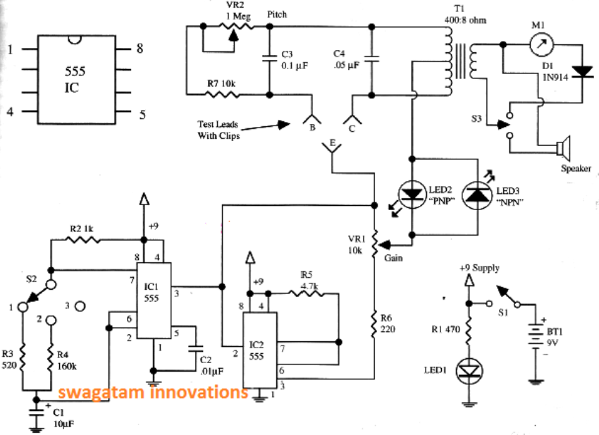
Designed By : Mr. Henry Bowman

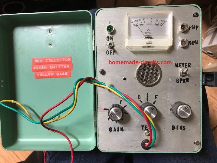
The following image shows the completed prototype of the transistor diode tester circuit by Mr. Henry.

transistor diode tester meter prototype

You'll also like:

  • MOSFET TESTERSimple MOSFET Tester and Sorter Circuit
  • capacitor testCapacitor Leakage Tester Circuit – Find Leaky Capacitors Quickly
  • digital panel voltmeter circuitDigital Voltmeter Circuit Using IC L7107
  • transistor tester circuit diagramAccurate Transistor Tester Circuits Explored

Filed Under: Meters and Testers Tagged With: Diode, Meter, Simple, Tester, Transistor

About Swagatam

I am an electronics engineer and doing practical hands-on work from more than 15 years now. Building real circuits, testing them and also making PCB layouts by myself. I really love doing all these things like inventing something new, designing electronics and also helping other people like hobby guys who want to make their own cool circuits at home.

And that is the main reason why I started this website homemade-circuits.com, to share different types of circuit ideas..

If you are having any kind of doubt or question related to circuits then just write down your question in the comment box below, I am like always checking, so I guarantee I will reply you for sure!

Previous Post: « 3D Moon-Sphere LED Driver with Charger and Dimmer Circuit
Next Post: Introduction to I2C LCD Adapter Module »

Reader Interactions

Comments

Clair Morrill says:
March 14, 2024 at 10:31 pm

Swagatam, I think that there would be a S2A and a S2B selector switch for the second monostable oscillator to select two different capacitors that would match the astable oscillator.

Reply
Swagatam says:
March 15, 2024 at 8:32 am

That’s right Clair, or maybe we can add a pot in series with R5.

Reply
Clair Morrill says:
March 14, 2024 at 10:00 am

Swagatam, what’s the value of the capacitor in the monostable oscillator circuit IC2, it looks like it’s missing

Reply
Swagatam says:
March 14, 2024 at 11:54 am

You are right Clair, it seems Mr. Henry forgot to insert the capacitor between pin6/7 of IC2 and ground.
Unfortunately, I am not sure about the value since I have not yet studied the working of the circuit fully.
You can try random values between 0.1uF and 1uF and check which one produces a valid result.

Reply

Need Help? Please Leave a Comment! We value your input—Kindly keep it relevant to the above topic! Cancel reply

Your email address will not be published. Required fields are marked *

Primary Sidebar

circuit simulator image

Subscribe to get New Circuits in your Email

Categories

  • Arduino Projects (95)
  • Audio and Amplifier Projects (133)
  • Automation Projects (18)
  • Automobile Electronics (103)
  • Battery Charger Circuits (87)
  • Datasheets and Components (109)
  • Electronics Theory (149)
  • Energy from Magnets (27)
  • Games and Sports Projects (11)
  • Grid and 3-Phase (20)
  • Health related Projects (27)
  • Home Electrical Circuits (13)
  • Indicator Circuits (16)
  • Inverter Circuits (95)
  • Lamps and Lights (159)
  • Meters and Testers (71)
  • Mini Projects (28)
  • Motor Controller (68)
  • Oscillator Circuits (28)
  • Pets and Pests (15)
  • Power Supply Circuits (91)
  • Remote Control Circuits (50)
  • Renewable Energy (12)
  • Security and Alarm (64)
  • Sensors and Detectors (106)
  • SMPS and Converters (34)
  • Solar Controller Circuits (60)
  • Temperature Controllers (43)
  • Timer and Delay Relay (49)
  • Voltage Control and Protection (42)
  • Water Controller (37)
  • Wireless Circuits (31)

Other Links

  • Privacy Policy
  • Cookie Policy
  • Disclaimer
  • Copyright
  • Videos
  • Sitemap

People also Search

555 Circuits | 741 Circuits | LM324 Circuits | LM338 Circuits | 4017 Circuits | Ultrasonic Projects | SMPS Projects | Christmas Projects | MOSFETs | Radio Circuits | Laser Circuits | PIR Projects |

Social Profiles

  • Twitter
  • YouTube
  • Instagram
  • Pinterest
  • My Facebook-Page
  • Stack Exchange
  • Linkedin

Recent Comments

  • Swagatam on Simple Tone Control Circuits
  • Ken on Simple Tone Control Circuits
  • Swagatam on Circuit Projects for Beginners and School Students
  • Swagatam on 10 Watt Stereo Amplifier Circuit Diagram
  • Swagatam on Triac Battery Charger Circuit

© 2026 · Swagatam Innovations