This simple refrigerator protector circuit is actually a delay ON timer circuit which makes sure that whenever a power failure occurs or in case abrupt power fluctuations take place, the refrigerator is never allowed to switch ON instantly, rather after a delay of a few moments.
Conventional Protection Features
Today most modern refrigerators are equipped with a protection feature which prevents the fridge from suddenly switching ON or OFF due to sudden power fluctuations or a sudden power restoration.
However, for those fridges which are not equipped with this feature, the following simple delay ON timer circuit can be applied to enable the refrigerator to switch ON after a certain delay, and only when the mains power has become stable.
Until this happens the circuit keeps the fridge switched OFF and monitors until the power has returned to a perfectly normal status.
NOTE: Please use a 50 ohm 1 watt resistor in series with mains input line, otherwise the zener diode may burn during power switch ON.
Circuit Operation
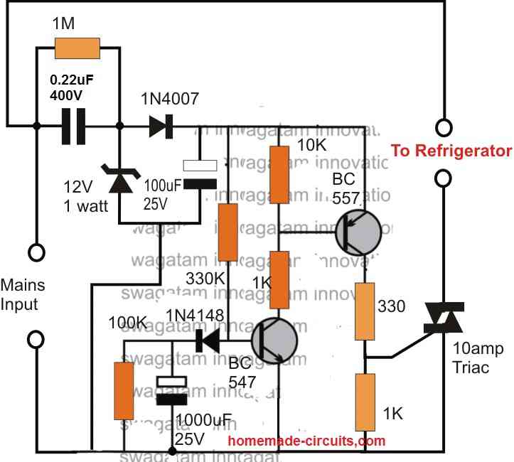
Referring to the above shown refrigerator protection circuit, we are able to witness a two transistor circuit which forms a very basic yet effective delay ON timer circuit, meaning this circuit switches ON its output after some delay, after power is applied to it.
The power supply to the circuit is derived from the mains via a transformerless power supply circuit
which is appropriately stabilized at 12V and fed to the delay circuit.
Whenever power is switched ON, may it be during the first initialization, or during a power failure situation, the associated 1000uF capacitor prevents the BC547 from switching ON at the onset, which in turn keeps the BC557 and the triac switched OFF. The load is therefore unable to receive power and stays switched OFF too.
However, the 1000uF now gradually begins charging via the 330K resistor and when the potential difference across it reaches the approximate total of transistor's biasing limit plus the emitter zener value (0.6 + 3 = 3.6V), the transistor begins switching ON which prompts the BC557 also to switch ON.
The triac now begins acquiring the required gate voltage and within moments switches ON the fridge.
The 1000uF capacitor stays charged as long as power is available to the circuit, and during power failures the capacitor discharges through the parallel 100k resistor so that it can get into the standby mode for the next delay ON cycle operation.
The time delay period can be accomplished by appropriately selecting the values of the 330K resistor, the 1000uF capacitor and the 3V zener diode, as per the user's preference.
This concludes the explanation for the proposed simple refrigerator protection circuit, for any related query please feel free to use the comment box.
Using Relay
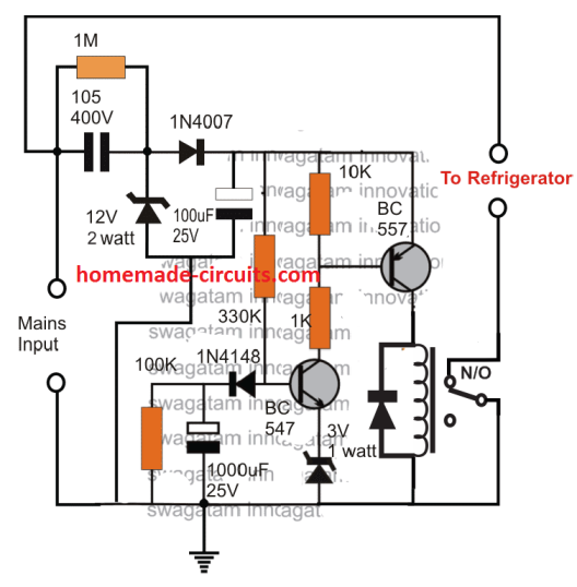
The above design can be used with a relay also as demonstrated below:
PCB Design (Triac)
WARNING: CIRCUIT IS NOT ISOLATED FROM MAINS... STRICT PRECAUTIONS MUST BE OBSERVED WHILE HANDLING THE DEVICE, WHILE IT'S IN AN UNENCLOSED CONDITION.


Questions & Answers
sir pls help
In your pir (https://www.homemade-circuits.com/2014/09/automatic-pir-controlled-fan-circuit.html) you mention that there is a delay in switching of fan..i dont want that delay..i need to switch off instantly..pls give me changes in circuit..so that i can use it for automatic faucet to prevent wastage of water
NVD, you can remove the 470uF capacitor for eliminating the delay effect
Sir mera laptop charge nahi ho raha hay mene dosra adptor lagaya tu thori dair charge howa phir nahi ho raha hay agar ap ko is k baray me maloom hay tu please help kar dain thank u.
Syed, the problem could be with the battery or the internal laptop circuit…can't say precisely without checking.
last question sir..i think i m not disturbing you..in below circuit
https://www.homemade-circuits.com/2016/07/touch-free-faucet-circuit.html
sirwhat is the value of resister R8 and R9 (not shown in fig)..sir is thereany substitute for 1uF 16v (cant find in store)..p1 and p2 are variable resistance is it right..is all resisters 1/4watt…i am going to make this circuit..hope itworks
you can use 10K for both the resistors
the 1uF is a filter capacitor so it's not critical, you can use any other higher value…
p1/p2 are presets, or trimpots
all resistors are 1/4 watt
thank you very much sir
Sir. The triac needs a heatsink?
Yes it will need a heatsink
hello swagatam,
the 3v, 1watt zener is not available here in my place. can i parallel 2x3V,1/2W zener instead?
hello jade,
1 watt is not required….1/2watt will be fine without issues.
Thank you so much sir
Sir i made a refrigerator delay on circuit using a 555 ic. I'm using a transformer based power supply and regulating it via 7812.
The problem am facing is i'm using a 25volts 1000mf cap with the transformer and the bridge rectifier.
When there is a change of power from genset to mains power, the circuit doesn't shut off as the change takes place in a second and the capacitor compensates this no power state and doesn't shut the circuit off.
I just wanted to know what rating of bleed resistor should i use. And should i use it before the ic 7812 or after the ic 7812.
Thanks.
Anirudh, you can try with a 1K 1/4 watt directly in parallel with the 1000uF capacitor and see the response
hello Swagatam,
Can I use 225 capacitor instead of 105?
hello jade, you can try it, if the triac fires correctly with it then it you can continue with it…..
dear sir i want this circuit for giving input to 12 V relay
please modify the above design as per the following design
https://www.homemade-circuits.com/2013/02/make-this-simple-delay-on-circuit.html
Sir,
Regarding the fridge protection circuit what are the wattage of the resistors.
Thanks
Noel, all resistors are 1/4 watt rated
Hi
Can the fridge protection circuit also be use for other items like tvs, other electronic equipment.
Regards
yes it can be used for any desired appliance or gadget.
Hi,
Can you design a circuit that can be used in a db box so that if there is load shedding or some power surge the entire plug points go off until voltage is stabilized at 240v when power comes back on.
Regards
Hi, I think you could apply the concept discussed in the following article and see if it suits your requirement.
https://www.homemade-circuits.com/highly-accurate-mains-high-and-low/
Hi
Thanks for the invaluable info really appreciate it.
Regards
It’s my pleasure!
Hi sir,
With regards to the high/low mains cut off circuit using two relays can the out put be connected direct to the db thereby protecting all appliances or must it be connected to each individual appliance.
Regards
Hi Noel, the 2 relay circuit is not required, you can use the single relay circuit and configure the relay contact in series with one of your DP lines and then you can apply it for safeguarding all the associated appliances.
Thank you much appreciated
You are welcome!
Hi sir,
Hope you are well.
Just want to know if you have a circuit to test eeproms.
Regards
Hi Noel, I have seen a few of them in some old magazines with me, if possible I’ll publish them here, but I am not sure whether the designs are still relevant or not.
Thanks appreciate it
Hi
Do you have a circuit for a 100w bass guitar amp.
Regards
Hi, you can try the following concept
https://www.homemade-circuits.com/how-to-make-outstanding-home-theater/
you can replace the shown amplifier design with the following circuit
https://www.homemade-circuits.com/how-to-make-simplest-100-watt-mosfet/
sir,
Can I use this circuit in widow type ac (aircondition)?
thanks and more power to you.
Hi Cecilio, yes you can use it for ACs also, in fact it can be used for any desired load!
Hello good afternoon. I like the circuit, but in my case it would be better with a relay … Because I never had much confidence in a triac .. Thank you in advance.
Thank you, for relay operation you can simply replace the 330/1K resistor at the collector of BC557 with a relay coil and with freewheeling diode
Hi, thanks for the quick response. You could modify the circuit with a relay … Thank you very much
I have updated it in the article…
Thanks Swag. I find your articles and circuits very detailed and informative. Especially to an electronics enthusiast such as myself.
Question: What should i change in the in the above refrigerator protector circuit when the input voltage is 110V.
Thanks in advance
Thanks Alex, for that you may have to employ 12V transformer based power supply, and modify the transistor stage so that the when the 12V drops to an equivalent 10V the relay trips OFF
Hi. I do have a question.
if by any reason, the circuit fail, does it inject 220 volt into output? or it will be higher than 220 volts?
Hi, if it fails, the refrigerator will either get a constant 220V supply or will be completely shut off, it cannot produce more than 220V because there’s no voltage boosting facility in the design.
so in worst case it causes no harm. it may only stop functioning. Am I right?
Yes that’s correct!
Hi Sawag, can we use VR insted of fixed resistor for adjusting delay time.
yes you can, replace the 330k with a 470 k or 1M pot. make sure to add a 10k resistor in series with the pot
” Please use a 50 ohm 1 watt resistor in series with mains input line, otherwise the zener diode may burn during power switch ON ”
Hi swagatham thanks for works – 50 ohm 1 watt resistor – where it exactly to be connected