This automatic plant watering circuit can be used for automatically sensing soil humidity and triggering a water pump when the ground gets parched below a predetermined level (adjustable).
Circuit Operation
The circuit is rather straightforward and uses a single IC 555 as the main active component.Referring to the automatic plant irrigation circuit shown below we can see the IC 555 is wired in a completely unique and in the quickest possible mode.
Here it's configured as a comparator, and works better than an opamp because the IC 555 has built in opamps which are at par with any single opamp and also the output of a 555 IC is able to sink sufficient current in order to drive a relay without a transistor driver stage.
The above features particularly makes the above design very simple, low cost and yet too effective with its functions.
The pin#2 here becomes the sensing pinout of the IC, and is held at ground level via R2 which must be calculated as per the desired soil humidity triggering threshold.
The points A and B can be seen fixed inside the soil which needs to be monitored for the intended automatic watering from the water pump.
As long as the points A and B senses some level of humidity corresponding to a resistance value which may be lower than R2, the IC 555 output is held low, which in turn keeps the relay deactivated.
However as the soil tends to get dryer, the resistance across the probes starts getting higher and at some moment of time it becomes higher than R2, creating a potential below 1/3rd supply voltage at pin#2 of IC555.
The above situation instantly prompts pin#3 of the IC to become high, triggering the connected relay.
The relay activation switches ON the water pump which now starts pumping water to the particular area of the soil via a distributing water channel.
As this happen, the soil gradually gets wetter and as soon as the predetermined level is reached, the probes immediately sense the lower resistance and revert the IC ouput pin#3 to a low again switching OFF the relay and the water pump consequently.
C1 ensures a slight hysteresis in the operations ensuring that the relay triggering is not sudden or abrupt, rather it switches only after sensing a genuine response from the soil conditions.
Circuit Diagram
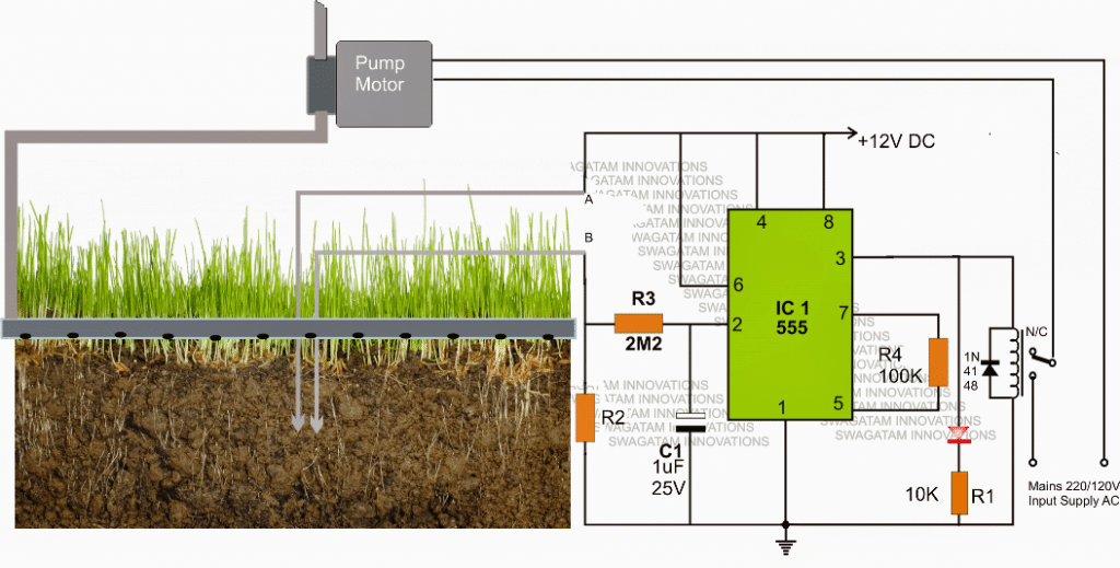
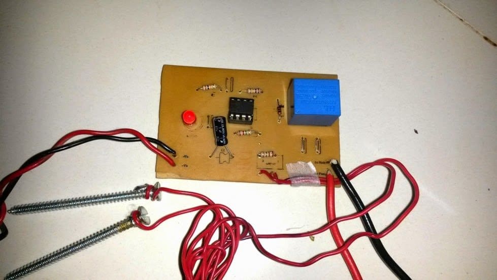
The above explained automatic plant irrigation circuit was successfully built and tested by Mr. Ajay Dussa.
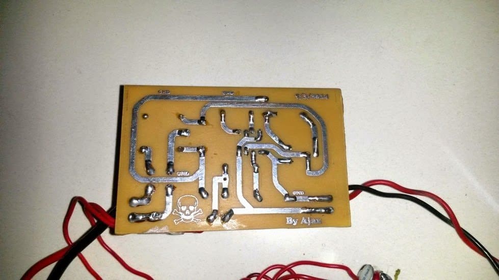
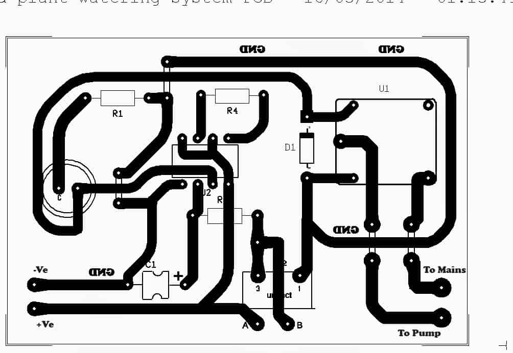
The following images show the prototype unit and the PCB design built by Mr. Ajay.
PCB Design
FOR A 741 OP AMP BASED CIRCUIT, YOU CAN REFER TO THIS ARTICLE.
Parts List
All resistors are 1/4 watt 5% CFR
- R1 = 10K
- R3 = 2M2
- R4 = 100K
- R2 = 1M preset or cermet
- C1 = 1uF/25V optional for creating delay effect on the relay
- Relay = 12V, 400 ohm SPDT
- Supply input = 12V/500mA DC
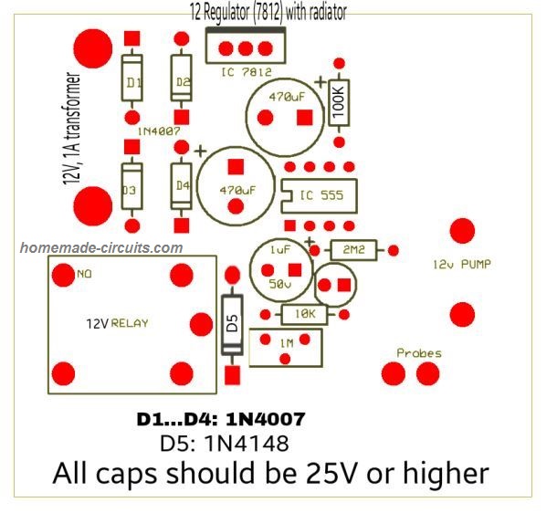
Another version of the PCB design is shown below. It was designed an contributed by: Alireza Ghasemi
Soil Moisture Sensor with Automatic Water Sprayer
The next article explains a 10 stage soil moisture sensor circuit with an integrated automatic water sprayer mechanism for restoring the critical condition of the soil. The idea was requested by Mr. Remy.
Technical Specifications
I come today asking for help making an automatic watering circuit to water my tomatoes for me.
I am requesting the use of a soil moisture sensor (cheap eBay style) to sense the moisture of the soil.
Then the moisture value is compared to a set value from a potentiometer maybe. If level is too low then a relay is turned on for a settable amount of time. After a shower the soil is measured again.
Rise repeat.
The ability to daisy chain many together would be a great help.
For wow factor I was thinking that having a few(3) leds light up as a scale to indicate the current moisture level would work well. Thank you for your time and experience.
I have learned much from you and hope to add this to my knowledge.
Remy
Circuit Diagram
The Design
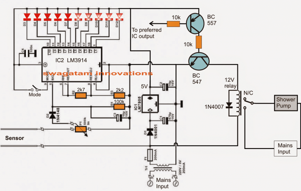
Referring to the given schematic we see a simple yet highly accurate soil moisture sensor circuit with an automatic preset water shower system for restoring the soil moisture level to optimum points.
The design is based on a single voltage sensor/LED driver IC LM3914 or a LM3915. The shown sensor pins which are basically two brass rods are configured as voltage sensors across the critical soil area where it may be inserted.
The voltage across these pins depend upon the level of moisture present across that particular soil area. This sensed voltage proportionate to the soil moisture level is applied across pin5 of the IC for the required comparison with an in-built reference voltage level.
The threshold level at which the shower pump is supposed to be switched ON is set by P1.
Depending upon this setting, the IC internal circuitry senses the soil moisture and produces a shifting sequential low logic across the shown 10 outputs starting from pin1 to pin10.
This sensed output across the relevant IC outputs are indicated by 10 respective LEDs which light up in sequence in response to the rising or depleting soil moisture levels.
Selecting Bar Mode and Dot Mode
The LED illumination sequencing style could be selected to simulate a bar mode or a dot mode by appropriately positioning the pin9 switch of the IC to either ON or OFF.
The stage comprising BC547 and BC557 constitute the relay driver stage for controlling the motor pump switching as per the user preference.
The base of the PNP transistor is appropriately integrated with any of the output pins of the IC depending at what moisture threshold the user wants the motor to be started or stopped.
For example suppose pin15 determines a particular moisture threshold level of the soil and the user feels it to be the unsafe level at which the motor needs to be started in order to restore the soil moisture, then this pinout could be chosen and hooked up with the base of the BC557 transistor for the discussed motor switching.
Once the motor is switched ON the soil is showered until its moisture level is restored to the desired level and this prompts the IC to revert its sequence from pin15 to pin14 and toward pin10, switching OFF the motor and the shower.
The above process keeps repeating making sure that the soil moisture level never goes down below the undesired parched condition.
Simple Transistorized Soil Watering System
Here's another automatic soil watering system that you can build. Its working mode is mainly the nonstop checking of soil moisture, and then responding to a drop beneath a preadjusted degree to set off the plant watering action. This design consists of a straightforward trigger circuit, that switches ON the relay RL for a degree of moisture in the soil and its conductivity which may be beneath the fixed level as adjusted by the 5 k preset.
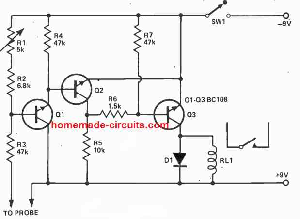
The conductivity inside the soil or mud is detected through a pair of probes coupled to the terminals as indicated in the diagram. The idea really is easy and very reliable, and will can work by using any supply voltage between 6 and 12 volts or even more, only if the supply voltage is perfectly compatible with the working voltage spec of the relay.
The relay contacts can be appropriately wired with a water pump or a water sprayer device for initiating the required automatic watering of the plant, each time a dry soil is detected and the relay is switched ON.
Using Water Control Valve
In the circuit below, whenever the amount of soil moisture exceeds a certain threshold, an electric water valve is shut off. One of the probes is attached to a positive 12-volt supply, while the other probe is hooked to the base of Q1.
The sensitivity is adjusted using resistor R4.
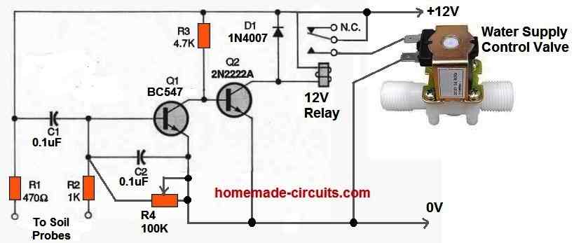
Once the moisture level falls below the predetermined level, Q1 switches off and Q2 switches on, turning ON the relay and supplying power to the water valve.
The water valve begins pouring water into the soil. When this happens the resistance between the two probes starts reducing as the amount of moisture around the probes rises.
Eventually significant current starts passing into the base of Q1 to switch it on and switch off Q2. As a result the relay turns off and the valve loses power. This instantly stops any further flow of water into the soil.
Corrosion Free Automatic Plant Watering Circuit
If the probes are not constructed from high-quality materials, electrolysis may happen and eventually impact how the circuit functions. Cleaning the probes frequently or using a circuit that uses an AC voltage on the probes are two solutions toward this issue.
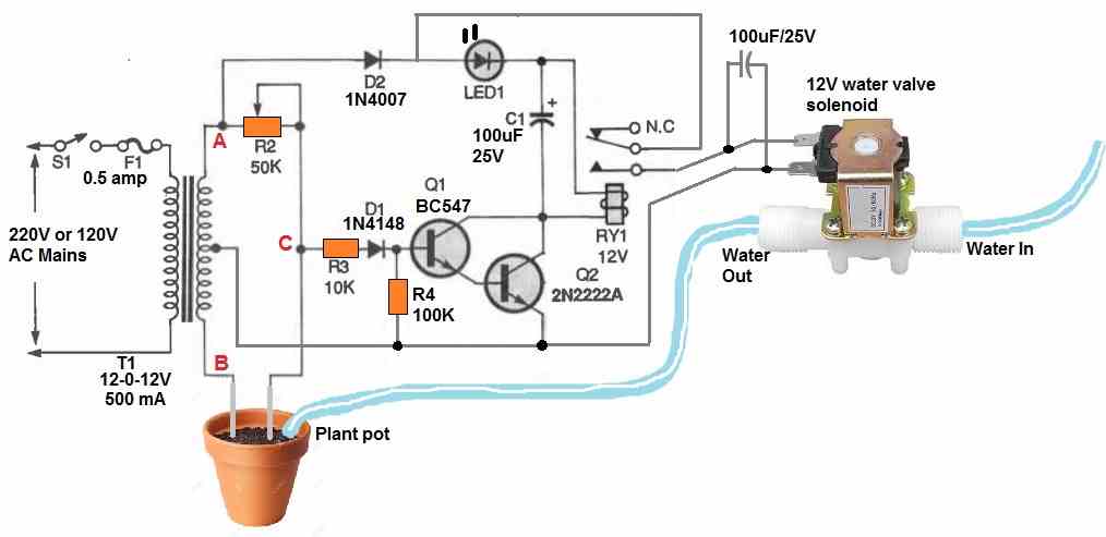
The diagram above displays an AC probe automatic plant watering valve control circuit with corrosion free probes. A 12-0-12V center tapped transformer is wired into an AC bridge circuit.
The soil or mud resistance between the probes along with R2 functions as a couple of variable components of the bridge circuit, with each half secondary winding of the transformer operating as one of the two fixed components.
In order to ascertain the magnitude of a component, such as resistance, inductance, or capacitance, an AC bridge circuit typically balances the bridge with the adjustable component and reads the component's magnitude at balance on the scale.
The output would be an AC signal which is 180 degrees out of phase and equivalent in amplitude on each side of balance.
If a typical AC bridge circuit had been employed for the anti-corrosion soil moisture detector, it would simply show when the ground resistance was close to the preset value of R4. The water valve would shut off once the bridge was balanced, but the water would still percolate into the ground, reducing the resistance between the probes.
As a result, the bridge would become unbalanced, reopening the water valve and flooding the plant soil. Not good at all.
The aforementioned circuit solves the issue by evaluating the bridge's output phase to the secondary of T1's "A" side. The relay would be activated and water would start flowing if the probes were first placed in dry soil with resistance values significantly greater than R4's predetermined resistance value.
It is because:
The voltage is provided to the relay via a 1N4007 diode and the LED whenever the "A" secondary winding of T1 changes from negative to positive.
Due to the resistance value of R4 being significantly smaller than the soil resistance, current is supplied via R3 and D1 to the base of Q1, switching it on.
However, at the same time the output at "C" is also starts becoming positive. Due to this Q2 turns on, switching ON the relay and turning on the water valve.
The bridge becomes balanced and the output voltage at "C" is zero as soon as the resistance across the probes reaches the predetermined value specified by R4. Transistors Q1 and Q2 now switch off, turning off the relay and blocking the water flow through the water control valve.
The bridge turns unstable in the opposite direction as the water seeps into the soil, however the relay is never switched ON.
It is because: Current is able to flow into the base of Q1 whenever the "B" secondary winding of T1 is positive, however no collector current is able to flow since the "A" secondary winding's voltage is 180 degrees out of phase and negative. D2 prevents that negative voltage from getting to the relay and transistor circuits.
The water valve won't turn on until the resistance measured across the probes is less than R4's value. To prevent the relay from stuttering, capacitor C1 is used to smooth out the oscillating DC power supply. Whenever the water valve is switched on, the LED flashes.


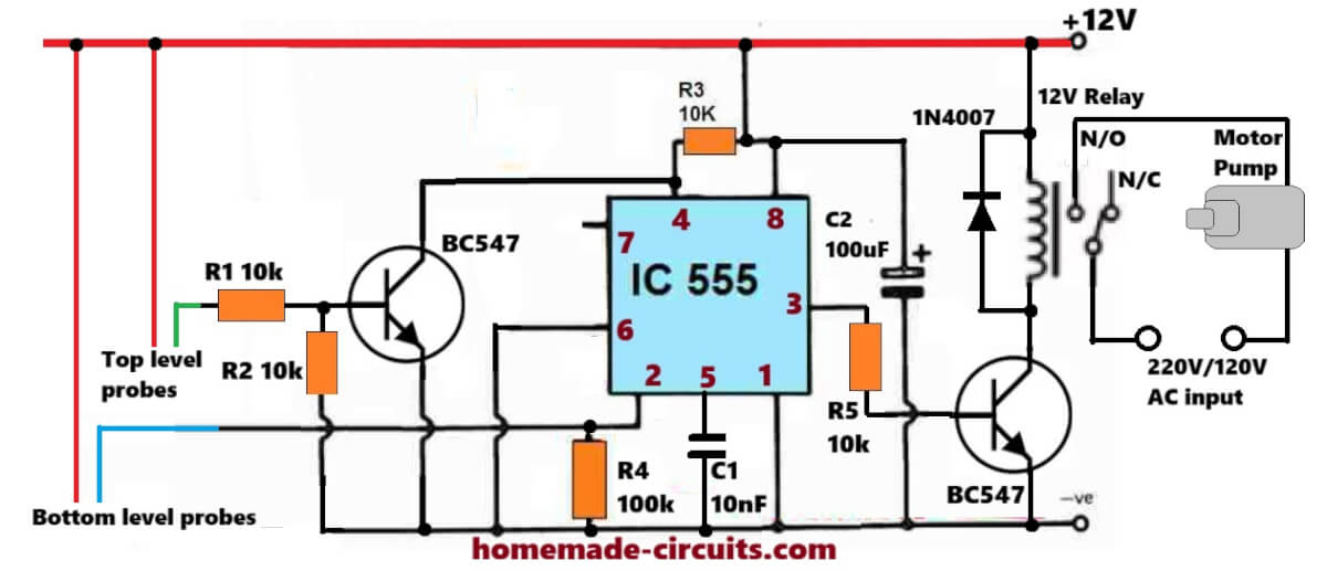

Discussion & Solutions
Oh!!!!Thank you for this circuit.Was waiting for this one.also I had sent you a mail on hitman2008@live.in regarding water controller.Please check that out.Also can you mention the value of R2…..I think it's missing….
You are welcome Ajay!
I have replied to your email, pls check it.
R2 can be replaced with a 2M2 pot for setting the soil moisture detection threshold.
Hi Mr swagatam,
i am new to your website and happy that there are so many good circuts,
I am in a instrumentation field, presently on some small project which need a 3.7vdc 750mAh lithium ion rechargable battery as a back up power, so kindly let me know the one good working circuit for 1)overcharge protection 2)immediate change over 3)low battery indication. As the one like yours Automatic micro UPS circuit.but now its for 3.7vdc
Bro, The input is not 3.7V, the requested circuit is for charging the 3.7v cells….
for charging 3.7v cells the input has to be 5v,
the diode cathode will obviously connect with the positive of the cell.
o o thanks bro.
how can i make battery indicator of 5 leds for 12v battery.
….you can refer to this article, it's a 10 LED circuit:
https://www.homemade-circuits.com/2013/08/make-this-10-step-battery-voltage.html
This is a very useful circuit sir, just made and installed it in my house, works very great. I've seen other circuits online…..but as always the best circuit with more affordability and durability is here….thank you for your innovative innovations….:-)
Thank you SS, I appreciate it a lot!
By the way I have published the phase neutral indicator circuit, but it's not as efficient as the original, because due to lack of time I couldn't experiment enough with it.
Nevertheless the results from it would be perfect.
Dear sir, thank you very much…….I've seen the circuit……no problem………you may design the the buzzer indication circuit when you are free and hav time….designing this circuit for me is not as important as doing your works…..but you're more concerned about others…….you're a boon to the electronics society all over the world…..and to people like me….
thank you very much,
ss.
Sir, by the way, I wanted to use a transformerless power supply for this circuit, can I do so sir,…? I would be happy if you could suggest a transformerless power supply circuit from this blog…also please tell me the current consumption of this circuit…….thank you sir……
Sure SS, as soon as I am free I'll upgrade the circuit appropriately:) I appreciate your involvement very much.
SS, it would be better to buy a 12v/1amp smps adapter from the market, a capacitive transformerless power supply could carry lethal mains AC due to its non-isolated topology.
for reference you can see the following design:
https://www.homemade-circuits.com/2011/12/cheap-yet-useful-transformerless-power.html
Hi sir can you help me how to calculate R2 in the circuit dry soil=1.7M ohms and wet soil=0.7M ohms and what should I include in my design report I was designing the soil moisture sensor.Thank you your circuit is very useful
Hi Sanele,
you can use a 2M preset for R2, connect the probes in a wet soil and adjust this preset until the LED and the relay just switch OFF
Oh…! Ok….thamk you sir…could you tell me the current consumption of the circuit sir,….thank you very much…..
it would be equal to relay current + 5mA
Dear sir,thank you very much, i followed your advice……and used 12v 1amp adapter(looked safer and better….:))….by the way, ive seen the circuit "earth leakage indicator circuit….thank you very very much sir…..ill make the circuit soon and give you the photos………….
thanks and regards..
ss.
Thank you dear SS, I appreciate it.
hye,sir
im electrical engneering student.
Im interested to do this project as my final project.
please send me information, complete project detail and programming details.
sankancu1724@gmail.com
Hi sankar, everything's explained in the article and the diagram, please click the diagram to enlarge for getting a clearer view.
can I know this circuit used microcontrolled(PIC) or not to control the time process?
there's no time factor here, and no microcontroller used.
hello sir, may i know whats the use of resistor connected between pin 5 and 7?
hello sonny, it's for creating some degree of hysteresis in the IC functioning…
Hii
I want to know all the components which are in the circuit.
At the output I am not knowing the components which are used.
Please tell me which components are used.
Hi Please click the diagram to enlarge, all the components are appropriately listed in the diagram itself.
The relay is a 12V SPDT
Hiii
In my place the single winded auto transformer is not available. So is there any option which I can replace instead of that.
Hi, there's no auto transformer used in the above explained circuit, so I am not sure where you intend to use it and why?
Above the input
It is acting as a switch N/C
What is the device used there.
There is winding near N/C what is that winding sir.
There is a winding near diode.
There is a switch.
What is that winding near the diode sir..
Near the diode there is a winding.
Is it inductor and there is a switch alsoo.
that's a relay. the inductor is the relay-coil, and the NC is one of its contacts
Motor ac or dc?
Motor ac or dc???
For C1 1u 25V ,can we change capacitor to 1u but 50V.does it effect to this circuit???
AC
It will do.
The phase goes to the relay contact….neutral directly with motor
Hey love the circuit, my only question is are both the diodes in the schematic zener diodes, also I have a 1n4004 and 1n4001 diode will they work
Are both the diodes in the scematic the same? And are the zener diodes? Also I have a 1n4004 and a 1n4001 will the work?
The cap is not polarity sensitive correct?
Thanks Josh, the red one is an LED, the black diode can be a 1N4007
yes that's correct
1n4004 will also do instead of 1N40007
damn, i cant find a 1uF Cap is there anything else
it's not critical any closer value would do, it's just for providing the IC some time delay before it responds to the soil conditions..
hey sorry for all the questions but i could not get it working, i think my ic555 chip was defected so i build a circuit to test this other chip i had and it seems to be working!. soo im going to try once more. im confused on replacing r2 for the pot where to i place the wiper and what value of red led is that 3v?
use a 1M pot for R2, use only its center and any of the outer leads, the third lead can be left open.
the LED can be any ordinary 5mm/20mA/2V type
hello sir my circuit work perfectly but it soil moisture sensitivity is to high when soil moisture is less then 10% then it will be work help me i want when soil moisture is 40 % then it will work i use 6vdc relay
hello faizan, increase the value of R2 to some higher level, keep increasing and checking the results until you have found the right value for R2.