In this post I have explained a simple IC 555 based self optimizing solar battery charger circuit with buck converter circuit that automatically sets and adjusts the charging voltage in response to the fading sunlight conditions, and tries to maintain an optimal charging power for the battery, regardless of the sun ray intensities.
Using a PWM Buck Converter Design
The attached PWM buck converter ensures an efficient conversion so that the panel is never subjected to stressful conditions.
I have already discussed one interesting solar PWM based MPPT type solar charger circuit, the following design may be considered an upgraded version of the same as it includes a buck converter stage making the design even more efficient than the previous counterpart.
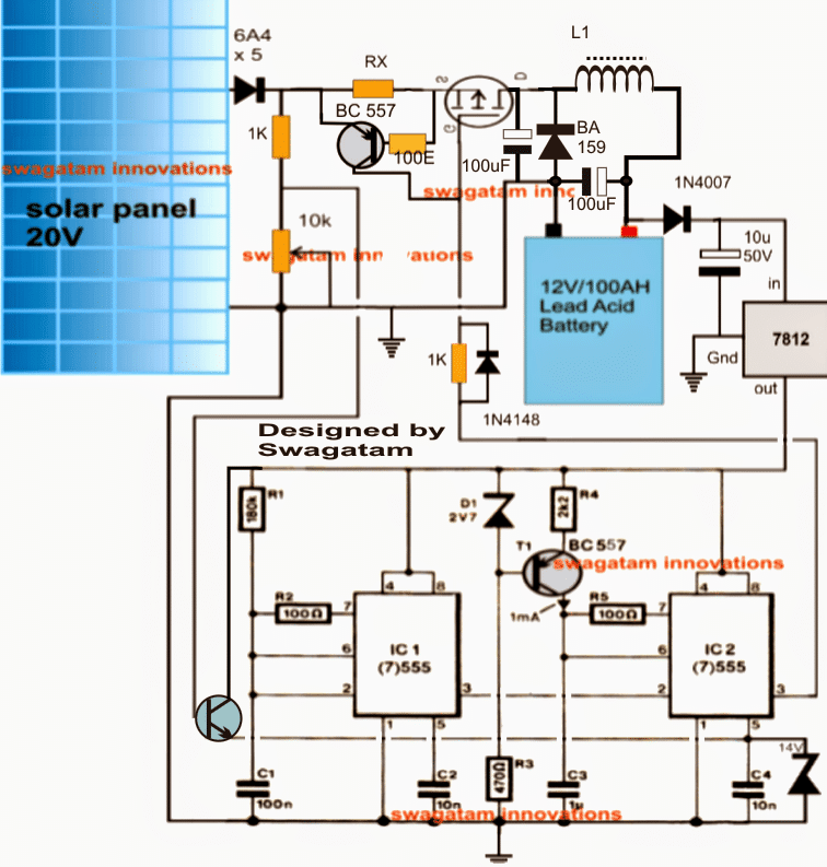
Note: Please connect a 1K resistor across pin5 and ground of IC2 for correct functioning of the circuit.
The proposed self optimizing solar battery charger circuit with buck converter circuit may be grasped with the help of the following explanation:
The circuit consists of three basic stages viz: the PWM solar voltage optimizer using couple of IC 555s in the the form of IC1 and IC2, the mosfet PWM current amplifier and the buck converter using L1 and the associated components.
IC1 is rigged to produce a frequency of about 80 Hz while IC2 is configured as a comparator and PWM generator.
The 80 Hz from IC 1 is fed to pin2 of IC2 which utilizes this frequency for manufacturing triangle waves across C1.... which are further compared with the instantaneous potentials at its pin5 for dimensioning the correct PWMs at its pin3.
The pin5 potential as may be seen in the diagram, is derived from the solar panel through a potential divider stage and a BJT common collector stgae.
The preset positioned with this potential divider is initially appropriately adjusted such that at the peak solar panel voltage the output from the buck converter produces the optimal magnitude of voltage suiting the connected battery's charging level.
Once the above is set rest is handled automatically by the IC1/IC2 stage.
During peak sunlight the PWMs get appropriately shortened ensuring minimum stress on the solar panel yet producing the correct optimal voltage for the battery due to the presence of the buck converter stage (a buck boost type of design is the most efficient method of reducing a voltage source without stressing the source parameters)
Now, as the sun light begins diminishing the voltage across the set potential divider also begins to drop proportionately which is detected at pin5 of IC2....on detecting this gradual deterioration of the sample voltage IC2 begins widening the PWMs so that the buck output is able to maintain the required optimal battery charging voltage, this implies that the battery continues to receive the correct amount of power regardless of the sun's retarding illumination.
L1 should be dimensioned appropriately such that it generates the approximate optimal voltage level for the battery when the solar panel is at its peak specification or in other words when the sunlight is in the most favorable position for the solar panel.
RX is introduced for determining and restricting the maximum charging current limit for the battery, it may calculated with the help of the following formula:
Rx = 0.7 x 10 / Battery AH
How to set up the above self optimizing solar battery charger circuit with buck converter circuit.
Suppose a 24 V peak solar panel is selected for charging a 12 V battery, the circuit may be set as instructed below:
Initially do not connect any battery at the output
Connect 24 V from an external C/DC adapter across the points where the solar panel input is required to be fed.
Connect a 12 V for the IC1/IC2 circuit from another AC/DC adapter.
Adjust the potential divider 10k preset until a potential of around 11.8 V is achieved at pin5 of IC2.
Next, through some trial error tweak and optimize the number of turns of L1 until a 14.5 V is measured across the output where the battery is required to be connected.
That's all! the circuit is now set and ready to be used with the intended solar panel for getting an optimized highly efficient PWM buck based charging procedures.
In the above self optimizing solar battery charger circuit with buck converter circuit I have tried to implement and extract an oppositely varying voltage and current output from the the circuit with respect to the sunlight, however a deeper investigation made me realize that actually it should not be responding oppositely rather corresponding to the sun light.
Because in MPpT we want to extract maximum power during the peak hour while also ensuring that the load does not hog the panel and its efficiency.
The following revised diagram now makes a better sense, let's try to analyze the design quickly:
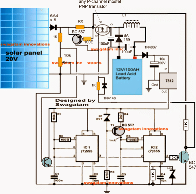
In the above updated design I have made the following important change:
I have added a NPN inverter at pin3 of IC 2 so that now the PWMs from IC 2 influences the mosfet to extract maximum power from the panel and reduces the power gradually as the sun light diminishes.
The PWM pulses along with the buck converter guarantees a perfect compatibility and maximum power extraction from the panel, but diminishes gradually in response to the sun's diminishing intensity.
However, the above set up makes sure about one important aspect, it ensures a balanced input/output power ratio which is always a key issue in MPPT chargers.
Further if in case the load tries to extract an excessive amount of current, the BC557 current limiter immediately comes into action preventing the disruption of the smooth functioning of the MPPT by cutting off power to the load during those periods.
Update
Contemplating the Finalized Design of an MPPT Circuit
After going through rigorous further assessments, I could finally conclude that the second theory discussed above cannot be correct. The first theory makes more sense since an MPPT is meant solely to extract and convert the extra volts into current that may be available from a solar panel.
For example suppose if the solar panel had 10V more than the load specs, then we would want to channelize this extra voltage to the buck converter through PWMs such that the buck converter is able to produce the specified amount of voltage to the load without loading any of the parameters.
In order to implement this, the PWM would need to be proportionately thinner while the sun was at the peak and releasing the extra volts.
However, as the sun power diminished, the PWMs would be required to broaden so that the buck converter was continuously enabled with the optimal amount of power for supplying the load at the specified rate regardless of the sun intensity.
To allow the above procedures to happen smoothly and optimally, the first design appears to be the most appropriate one and the one that could fulfill the above requirement correctly.
Therefore the second design could be simply discarded and the first design finalized as the correct 555 based MPT circuit.
I did not find it appropriate to delete the second design because there are various comments that seems to be linked with the second design, and removing it could make the discussion confusing for the readers, therefore I decided to keep the details as is and clarify the position with this explanation.



Questions & Answers
Hi, Can i use wind turbine and solar panel pluged in parallel?
Hi, yes it can be done through separate bridge rectifiers for the two sources.
Can you show me how should I modify your schematic to work?
you will have to make two bridge rectifier networks using appropriately rated diodes. Next, make the positives and the negatives of these rectifiers common and connect them with the input of the above circuit.
After this you can integrate the outputs of the wind turbine and solar panel to the inputs of the two bridge rectifiers….I hope you got it.
hello Mr swagatam all the best for the new year sir if I am using a n channel fet insted and do the modification in connections as u staled in anothe post what type of transistor should I use as current limitor on connected on the source side of the fet same PNP or use a NPN . thank u
Hello unknown, it's better to go with a P channel because using an Nchannel will require quite a few modifications to be done….it'll be difficult for me to explain it here, if possible I'll try to update the article with a Nchannel version.
hello Mr Swagatam I got the p channel today I would like to tell u the results I got because i dont know if this is normal I conect the fet just as how u design it on the circuit I can vary the voltage on the gate of the fet yes but I realise even when the gate voltage is 0 volts the battery is still getting some voltage to charge the battery is this normal. When I use a n channel and connect it as how u connect the fet in the I/V mppt when gate voltage is 0 volt no voltage goes accross to charge the battery please help me here Sir thank you Alex
hello unknown,
with higher voltage at pin5 the pin3 of IC2 will generate wider PWMs which will constrict the P fet conduction causing it to produce lesser amount of voltage and with lower voltage at pin5 it will become the opposite proportionately.
the idea is to derive more conduction from the P fet as the sun goes down and vice versa…so at 0 volts the PWMs will be narrowest allowing the P channel to conduct fully and therefore it will conduct whatever voltage is applied across its source…
Thank u Mr swagatam for ur reply I just understnd how the P channel fet works now in this circuit u are trying to let the panel work at abetter voltage even when the sunlight is lower . So when I am getting charge voltage even at 0 volt on the gate is normal Sir. I will recheck it again tomorrow because I think this thing can work Sir.In ur last reply I am not too clear on ur explanation of the collector voltage on the npn transistor . If its the one that gets the signal from the panel network resistors well this collector is connected to the regulator v please clear me up on this . Thank u Alex
yes that's correct, the idea is to get a self adjusting/optimizing output from the panel such that a constant voltage is achieved regardless of the changing sun intensity, and simultaneously making sure the panel does not get loaded inefficiently…
thank u Mr Swagatam for your reply. I did not have any P channel at the moment so I did a modification and used a n channel configured as how u did it in the I/V tracker circuit with source going to ground and drain going to battery negative.I am trying to understand the concept. When the sun is at its fullest I should adjust the pot to get about 11v at pin 5 I asume up to 14v max is this correct sir. When the sunshine decreases this voltage will also decrease which causes the fet to be less fully on is this correct. If my understanding is wrong please correct me here Sir. If I build the first circuit with just the resistor network and pot I am able to adjust the voltage from 0 to 12v on the gate fine when I use the npn transistor I am not able to adjust from 0 but from about 9v to 12v sir so I amwondering if something is wrong with the config Sir. , First i did the test manually I used a 10k varable pot network connected to the 12v and ground using the centre tap conected to pin 5 and I am able to vary and find an optimal point for the panel so is just to get the circuit to work from the network resistors connected to the panel sir As soon as u help me out here I am able to tell u and everyone the results. Thank u Sir i await your re[ply
check the voltage at the collector of the NPN.it should decrease as the pin5 voltage is increased and vice versa due to bigger PWMs at the base of the NPN.
decreasing voltage at the collector of the NPN will proportionately force the N channel to conduct lesser and produce lesser voltage for the battery and vice versa.
Meaning when the sun light diminishes the N channel will conduct proportionately more ensuring a proportionate increase in the charging voltage for the battery as the sun light goes down…and vice versa.
thank u MR Swagataam I tried again today with the P channel The results are like this without using the npn transistor from the panel network resistors I can vary the gate voltage from 0 to about 12v on the gate of the fet. When ever I put the npn transistor in place I can only vary from 9v up to 12v on the gate although the base voltage which is coming from the panel network is being varied from 0 to 12v. there is this constant 9v at the emmiter of this transitor which goes on to the gate of the fet and I think this is not right . Please correct me on this Sir. Alex
Alex, a NPN is required only if an Nfet is used at the control stage…with a P channel fet the gate can be directly connected to the IC2 pin 3 as shown in the diagram, otherwise it'll give opposite and undesirable results
thank u mR Swagatam I am not speaking about that transistor to drive the gate I am talking about the transistor on the left that is connected between the PANEL resistor network and the pin 5 Sir. On the emmiter I have 9v minimum and this can vary up to 12v and this is what is happening to the gate voltage. While on the base of this transistor the voltage is varying according to the pot from zero to 12 Sir so I am asking if this is normal because this 9v constant on the gate of the fet will cause it to conduct according to this v I suppose. Please help me here sir. Thank u Alex
OK I got it, it's happening due to the 555 internal resistor set up, which is holding the level to 2/3 Vcc….do this, add a 1K resistor across pin5 and ground and check the response….
ok Mr swagatam I did some more tests today with a P channel fet and got some better results , I see where u say as the sunshine increases the voltage on the gate would increase causing the fet to conduct less and visi versa. This principle should work Sir. what I want to understand fully, is it that say a panel gives maximum current at a certain voltage when charging a battery.So if I can turn that pot when the sun is at its peak and find that spot with a watt meter and set it there then the rest of lower setting would autommatically fall in place as the sunshine goes down still finding the best spot for the panel to work in .Just want to know if I get the concept right. Thank u and waiting for ur reply on this post and the others before.
Hello Alex, yes you can try that…
hello Mr Swagatam we really appreciate your simple way of teaching us the things that look so difficult and impossible. Today I really found out that optimising your panel at the better working voltage works Sir. I used a bulb to conect straight to the panel the bulb came on but the volt went down to about 6.5v this was really in the evening. I connect the bulb at the output of the mppt circuit above and was able to get a brighter light from the bulb and this time it was optimaised at 12.8v so u see that your concept will work Sir. The only the problem I am having is to get a smooth adjustment at the gate of the fet Sir and remember I am using a N channel in the design.I can get a smooth adjustment from about 0 to 9v but between 9 and 11 its hard to get a smooth adjustment so right here the panel voltage will jump from about 25 to 29v I am using 35v panel to charge 24v bank . This is happening at the gate of the fet At the pot there is smooth adjusment right on to pin5 and I find out that right about here is the optimal point on the panel just about 26 to 28v. I am using the modification u recomend using a npn transistor to the gate of the fet to change around the opposite voltage change Sir. Please tell me what u thinkcould be the problem before I proceed further . Thank u
hello Alex, It will be difficult to assess this problem without practically seeing it, are you sure your pot is alright?
Or you can try adding a 1K pot in series with 10k pot ground terminal, this can be used for fine tuning at the rough area.
Thank u Mr Swagatam one quick question sir if I am using N CHANNEL fet do I still have to use the npn transistor that connects from the panel resistor network divider and connects to pin 5 or I can run it straight (Using N channel Fet )
Mr. Alex, yes you'll have to include the transistor under all circumstances, it is there to increase the current response at pin5 ……otherwise pin5 will not respond properly.
ok sir thank u I got that part right and added the 1k resistor from pin 5 to ground to bring the 9v which i had on pin 5 .I also added the other transistor from pin 3 to the gate of the fet and this also respond correctly. only where I need the fine tune but I will work on that Now the circuit is complete just to do a proper adjustment on the gate voltage setting with the pot to get it to work in the optimised panel voltage. I am wondering if I use a watt meter at the peak of the sunshine to check the highest wattage I can achieve from the panel if this would be the same as setting up as how u describe above to do the setting up sir.
Mr swagatam could u give us some more detail on the coil about how many turns to start with thank u
you can begin with a 21 SWG, or a 0.6mm magnet wire, 20 to 30 turns wound over a ferrite ring, or if a ferrite ring is not available you can try it on any other suitable ferrite core, an EE core would be perfect.
check and optimize the voltage to the required charging level by adjusting the 10k pot, do this without connecting a battery.
you can also try replacing the pin5 1K resistor with a 1K pot for adjusting the above response, and for getting an optional tweaking facility…
make sure you connect a 100 ohm resistor in series with the 1K pot to safeguard the BC547
Thank u Mr Swagatam I will get the coil turns right tomorrow Sir. Please expand on the term optimise voltage. Is this the floating charge voltage of the connected battery or it is the voltage at which the panel will work best SIr please help me to get the full understanding here so ur design can be fully tested sir. what is this voltage for a 24v battery bank and 48v battery bank. I await ur replr thank u
Mr. Alex, by optimizing I mean setting up the correct charging voltage at the output regardless of the input voltage. For 12V it should be around 14.4V, for 24V it should be 28.8V and for 48V it should be 57.6V
Ok now i understand u Sir I will try that today and tell u the results and this should be set at the peak of the sunshine because if I am putting out more than this amount ov volt it would cause the panel to be loaded down and become less efficient sir alex
IMPORTANT I forgot to tell u Mr Swagatam that the problem I was having do a fine tune adjustment on the voltage. Today I found out that when the sun was gone down in the evening I was able to do a better fine tune adjustment on the voltage . Could this be a high current problem please look into tis Sir Alex thnak u
No it's not about high current, your buck converter may not be working correctly, it must be set correctly, the problem may be in this stage
hello Mr Swagatam I am back to report todays findings on the mppt.I am having some different effects maybe because I am using a slightly modified circuit to the above one Sir As I said I am using a n channel fet . The connection of the fet is just as how u connected it in the i/v tracker circuit https://www.homemade-circuits.com/2013/09/iv-tracker-circuit-for-solar-mppt.html source to ground and drain to -v of battery with + pole of battery going to + of panel. This is how it works I am not able to adjust the output voltage it is just sending out the full panel volts no matter the pot setting but on the other hand I am able to measure full open panel voltage right down to battery volt when it connects directly with the battery . This I can measure at the input of the mppt Sir so I just set it to 28.8v at full sunshine dont know if this process is right please correct me where I went wrong sir I await ur reply Alex
Thanks Alex, make sure your buck converter is working correctly, check it separately by supplying the voltage from a power supply instead of the panel and by applying some constant high frequency at the gate of the mosfet.
The number of turns should decide how much voltage you get at the output, it will be directly proportional.
Once this is done you can go ahead and check whether pin3 of IC2 is generating varying PWMs in response to a varying pin5 voltage
hello mr Swagatam have sent an email to u with the diagram please check this for me sir and see if there is any mistake . Thank u
hello Mr.Alex, your NPN/FET connections with pin3 of IC2 are correct but the buck circuit is wrongly done
thank u Mr Swagatam could u send me the right connections Sir i would really appreciate this as early s possible I await ur reply on this Alex
Alex, you can use the buck circuit as shown in the diagram, just change the fet polarity, connect the source with the buck converter and drain with the solar panel.
….make sure the NPN transistor's collector resistor connects with the solar panel positive.
thank u Sir. Which npn transistor u are talking about . is it the one that drives the fet gate. If this is the one suppose I am using a 48v system I would have to change the resistor value . Right now it is connected to the regulator positive that supplys the rest of the ics sir is this right . I await ur reply thank u Alex
thank u sir tomorow I will try this connection please clarify the npn collector connections. Thank u Alex
Alex, yes that's right, make it 22k and connect it with panel positive.
Thank u Sir I will check it today and let u know
Alex
hello Mr Swagatam I sent you a drawing of the circuit please check to see if the connections are correct Sir thank u I await your reply Alex
hello alex, it's correct, just connect a 12V zener between collector and ground of the NPN transistor.
I can't understand why you connect the diode in series with the coil, it should be between source and ground as given in the diagram (BA159)
Thank u Mr Swagatam for the correction. I put the diode just because u had used it in one of ur circuits for reverse protection. I will soon try the new connection because right now I tried the old connection and I think I am getting some better results than when I connected the panels directly to the battery it is the first for a long time i see my batterys going to 54v plus i normally go like 52.6v so I have ordered a watt meter to actually see what is happening in real life Sir today when the sun was hottest the panels were putting out 58v there about.I think youe concept is right sir it will just take a few ddays to get the meter and then I can tell u exactly what is happening. I will just leave it again tommorow and see how well it works sir. So in my case using a Nchannel fet sir in the evening when the sun is weakest I should be getting about 10v at the GATE of the fet or more and in the mid day about how much because today I was getting about 11.4 at mid day and in the evening I was having about 12.2 dont know if this setting is right sir . I await ur reply . Thank u Alex
Mr Alex, according to me first you must confirm whether your buck converter is working correctly or nort, if it doesn't work correctly then you won't get the optimal effect from the design, so first check it separately using a 24V power supply, such that the buck outputs the required 14V from it, once this is done you may proceed with the 555 integration and the preset settings.
hello Mr Swagatam I think I saw u had a circuit of an i/v tracker that used a buck converter at the output not the transformer output . Could u send me the link sir . thank u alex
please type I/V tracker in the search box and you should be able to get it right away…
thank u Mr Swagatam . What i was askinng is if I should be having more than 10 v at the gates of the fet at any time in that this is the FULLY TURN ON VOLTAGE for the fet. The voltage at pin 5 is normally a bit higher than at the gate sir. I will check to make sure the buck converter is working as how u say it should work but please keep in mind I am working on 48v system sir Alex
Alex, a 48V panel will be able to produce at least 12V even under worst conditions, the gate would be receiving the voltage from the collector resistor of the NPN not from the 555 pin3, make sure you have added a zener diode across the collector and ground as explained earlier.
hello Mr Swagatam seems I am missing something here. U said the gate would be getting the voltage from the collector of the npn transistor and not from pin 3 ? So would'nt I still have the 10k connected to the base of the npn and being driven from pin 3. of ic 2 sir Alex
Alex, the pin3 needs to be connected to the base of the NPN so that it can conduct and produce inverted voltage at its collector for the fet gate to respond.
ok thank u sir I will make a test today agin Alex
hello Mr Swagatam I am just waiting on the watt meter to arrive so I can do a proper test with the mppt controller and with the panel directly connected to battery Sir so as soon as this is done i will let u know the result Alex
OK great, thanks!
hello MrSwagatam I got the meter late this evening I did just a little test before the sun went down. I could see the difference in wattage with the mppt sir . if I use the pot and make a direct connection with panel and battery meaning panel output voltage reading 13v same as battery I get about 26 watts out of the panel but when I optimise the panel voltage to about 16v I start to get about 46 watts out of the panel Sir. I just need to get some time to do a proper setting and test it for a day. As soon as I do this I will let u know if I succeed with that part of the circuit Sir but for now I can safely say optimisiing the panel voltage give more wattage through ur circuit it works . Thank u Sir keep the good work going it pays off. I will soon give u further report. Allex
Thanks Alex, good observation.
we'll wait for more updates from you.
Hello Mr Swagatam I still dont get the time to go back and do some thorough test on the mppt as yet I am very busy at the moment so I just left it connected to my battery system from the last time. I wish u could post the circuit using a npn fet so i can see the right connections as soon as u can sir. Thank u Alex
Hello Mr. Alex, if time permits I'll try to update it,
the diagram that you had sent in my email was OK, so there's no issues with your NPN design
Ok Mr Swagatam I will do some test on it again on Monday I should have some time to try the npn config and let u know Sir thank u Alex
you are welcome Alex.
hello Mr Swagatam I am back again today I did some more testing onthe mppt. Remembering now my circuit is 48v system and using N channel fet as the circuit I sent to u. I am having a little issue I know u can help me with. One is I need to know how the voltage at the collector of the npn transistor that drive the gate of the fet should behave. What I find happening is when the sunlight increase the voltage at the collector coming through this 20k resistor also increase because there is a higher panel voltage flowing and I think at high sunshine i should have less voltage on the gate to alow less voltage at this time to optimise the panel Sir ( being a n channel fet ) as how I understand ur concept. So this is a concern I need to understand how here should work. Should I have a zener here?. I still have a problem to get a smooth vary in the voltage also sir I a having about 80v at full sunshine I can vary smoothly from 0 to about 25v then it jumps right up to 80v no matter how I turn the pot slowly this is with battery not connected.( with battery it seems I can get a bettery control ) but I want to fix the problems one at a time.. Could this be a improper operation of the pwm section .Please help me first to understand the voltage through this resistor from panel to transistor sir I await ur reply. Thank u sir Alex
Hello Alex, I think it would be better to connect the NPN collector resistor with the circuit 12V supply.
Also try the following alternative:
remove the NPN and connect the fet directly with pun3 of IC2
but before this replace the pin5 BC547 with a BC557, the base connection will be as it is that is to the solar panel preset, but its emitter will now connect with pin5 of IC2 and collector to ground, for this modification the 1K resistor can be removed from pin5 of IC
just to confirm with u and letall readers know for sure that optimising of panel voltage works better than connecting straight panel to battery Mr Swagatam concept is right
thank u Mr Swagatam for the reply I tried the bc557 today but I think the connection u gave me is wrong or the wrong type of transistor . when I connect it works but it is giving me the same response as what is happening at the panel resistor divider remember I need the opposite to happen because I am using aN channel fet sir. thank u Alex
Alex, the connection I provided you is correct, you may have to connect a 1K across positive and pin5 additionally.
A BC557 will produce exactly the opposite than BC547…. both cannot be the same.
you must check the pin5 and pin3 response by supplying a varying input from a power supply before checking the final output results
thank u sir I will try adding a resistor today and see the results and let u know Alex
Alex, please don't try it because I am finding it slightly confusing to simulate the results so it's better to stick with the ongoing procedures.
a NPN at pin3 can be avoided if a NOT gate is available and used here, its output will produce exactly the opposite PWMs which may be directly compatible with a N fet.
i love the work your doing can you help me with a parts list and how i can home make the L1
thanks, please click the diagram to enlarge it, the part values are all provided in the diagram itself.
L1 will need to be made with some trial and error, start with 20 turns mm wire over a ferrite rod.
…20 turns, 1mm super enameled copper wire over a 1 cm thick ferrite rod
hello Mr Swagatam I eventually got some good results now sir As u always say u give us the concept and we should do a bit of tweeking to get things to work. I used the 12 v supply that supply the ics to connect to the 1k that connects to the collector of the npn transistor that drive the gate of the fet and this voltage is now stable regardless of sunshine because this comes through a 12v regulator. Now the gate voltage goes with increase sunshine and visi versa when the sun goes down and in so doing it optimises the panel voltage. Dont know if the Pchannel fets I am getting are not good or what but I keep on getting the panel voltage through the gate and this in turn burn the pwm ic so I stick to the n channel version Sir . I am not able to use a watt meter on this 48v system because my meter canot handle this high voltage but I built it at 12v using the watt meter and I see where the wattage was increased with ur circuit Sir I really appreciate your effort and support to us..This design was a test one so I will get new parts and build the final product.I need to add one more fets to handle more current so I can allow the fet to run cooler. Can I just parallel the other fets feeding each gate with a 10 ohm and then connecting back to the 1k coming from pin 3. would a totem help to make a better drive circuit Sir I awai ur reply Thank u Alex
hello Alex, that's very encouraging, thanks for all the efforts you have carried out for verifying the above design.
According to me, all fets have a high gate resistance so the connected input may not be affected by the source potential, however for safety sake it would be a good approach to include a BJT stage in between just as you have done.
for increasing power you can simply add another mosfet in parallel with the existing one with a separate 10 ohm gate resistor,
a totem pole is a different concept, it's not relevant here.
…you can include an LED from pin3 to ground just for getting a direct visual indication regarding the PWM variations with respect to the sun ray intensity on the panel. the response should be in reverse…. that is the LED getting brighter as the sun goes down
thank u Mr swagatam for the info . What about the frequency I was asking about using a higher frequency if this would be better I am now building the finish project so I wanted to know because I have raised it to 9khz. The tuning of this circuit is really critical Mr Swagatam inorder for u to get the right volts out with the right gate voltage for each setting but I am learning and I will soon pass it on to the post . i await ur reply. Thank u Alex
hello Alex, use 20KHz frequency for getting an optimal response from the ferrite inductor.
the tuning can be done by supplying the assumed max voltage to the circuit and adjust the solar preset such that the voltage at the output of the buck converter reaches the required battery voltage.
This must be done without connecting any battery and the 555 stages powered from an external 12V source.
thank u Mr Swagatam on the frequency I will do the adjustment to 20khz. I have finis building the final circuit now but I just want to get a fine tuning on the voltage. What components around the pwm section is responsible the even tuning of the voltage . Meaning . Remember I am using 48v system. I can vary from 0 to about 57v then it jumps up to about 59v I cannot get a fine tuning between 57 and 59v and this is about where the optimal voltage setting is for 48v battery charging. When u check the voltage from the panel network resistor this is evenly adjusted up and down Sir but after the pwm out u will have say 10.334v and then it jumps down to 9.01v and in between this is where i would get about 58v. Please help me on this sir . I added one more fet and its running more cooler sir just this little part and the circuit is a 100% success sir. I used it today anyway on the system and it worked all day charging up to 57v on a 750Ah battery bank. I await ur reply on this issue sir alex
that's great going Alex, keep it up.
the voltage at pin5 if IC2 basically decides the width of the pulses at pin3 of IC2. at zero volts this will be the narrowest and at supply voltage level it should be the widest.
to confirm this you can connect a DC voltmeter across pin3 and ground, the reading must show a gradual increase from 0 to 5V in response to a gradual increase of voltage at the base of the BC547 connected to the solar panel potential divider network.
for getting a fine tuning feature you can try connecting a 1K preset in series with the solar panel 10k preset and set both of these for getting the desired response from the circuit
Thank u Mr Swagatam on the fine tuninf variable resistor it di d work Sir I was able to do a better fine tuning on the gate voltage. I realise that setting up the gate voltage is very crusial in the proper operation of the circuit if it is set too high (well in my case being 48v system ) u get an increase in gate volts as the sun shine increases but if set about 10.2 it works as how it should in regards to the sunshine. Today was not a sunny day so I hope I can do a final test on this part monday. I dont know if u got the post I sent about the power supply section.. I want u to describe a circuit using a transistor to switch on a regulator after the sun is up in the morning and this regulator will power this circuit sir. Can I put the led accross the gate to ground orthis will affect the working . I await ur reply sir Alex
Alex, I did not get the power supply info emailed to me, yes you can put an LED with a series 1K resistor but put it across pin3 and ground of IC2
ok r Swagatam please check ur email I sent it to u sir Alex
Alex, I could not understand your exact requirement, please specify it here once again point wise.
Hello Mr Swagatam dont seems u are getting my posts or email sir or maybe u are busy please let me know sir Alex
Hello Alex, I have already replied this in your previous comment, may be you missed it.
I could not properly understand what you mentioned in your email, you said about some voltage regulator which would switch ON when sunshine is detected….please elaborate more.
hello Mr swagatam as I said my circuit it not eactly like the above circuit. The FET and BATTERY connection is just as the circuit link I have past here for the i/v tracker4.bp.blogspot.com/-MPI5uQR6ff8/Uj2tJFDcVYI/AAAAAAAAFR8/cK1oeI716Hg/s1600/iv+curve+tracker+circuit.pnthe rest of the circuit remains as the above one so I want you to describe a circuit to power this circuit that is 12v regulated from the panel voltage sir insted of powering it from the battery side as described above Alex
Hello Mr. Alex, you can do one modification in the above circuit, remove the buck converter stage from its shown position and place it in between the solar panel output and the preset voltage divider.
The buck converter can be set to regulate the solar voltage to 12V and then feed the rest of the circuit.
To be precise just place the buck converter as explained above in the following circuit:
https://www.homemade-circuits.com/2013/04/simple-solar-mppt-circuit-using-ic555.html
i have sent a photo to ur email sir Alex
Hello Mr Swagatam sorry for the long silence I was busy doing some other work which kept me busy sir. I just saw your modification.In that I am using a n channel fet this would not apply to me sir. I already have a npn transistor between the gate and pin 3 sir which cause the gate voltage to get lesser when he sun is hotter and higher when the sun is less in sunshine. Please advice me here sir. My circuit is working so far i will upload the circuit I need u to configure for me soon . I await ur reply sir Alex
Hello Alex, just connect the pin3 of IC2 directly with the base of the N-fet remove the NPN stage entirely
and check the results, you may have to do some readjustments and realignments for the new design.
make sure you have a 1K resistor across pin5 and ground of IC 2
It's not handling 20V, rather only what may develop across Rx, around 0.6V
you can directly connect pin3 to the gate of an N-fet gate….make sure the N-fet is correctly configured with the buck converter.
source to coil…..drain to panel
hello sir did u get my last post on the setting I have on my circuit in the full sunshine and in the evening sir
hello alex, which post are you referring to? the above post was the last message which I received from you recently….
Hello Mr Swagatam I was having some problem send post to ur site a few days ago. What I was saying before was according to ur concept we need to set the panel voltage at the best optimise voltage so the panel can give max wattage. So at max sunshine this voltage would be about 17v for a 20v panel if we try to send the full 20v at max sunshine we get less wattage but when the sun goes down we would want to get this full 20v inthat the current is now falling. This is how I understand ur concept so in my case being 48v I allow about 58v at full sunshine and this is about where I det the best wattage sir as the sunshine gets less I allow more volts to compenste for the falling current. So at full sunshine I have about 9.8v on the gate of the fet and in the late evening it goes to about 11.5v to allow more volts . According to ur last design it is the opposite sir please help me on this if I am wrong. Thank u for ur help looking for ur response Alex
Hello Mr. Alex, please ignore my previous concept as it may not help you to achieve MPPT.
The idea here is to set the circuit for achieving the input/output wattage ratio as close as possible to unity that is 1
for example suppose if your panel specs are 56V@1amp that's = 56 watts, and you intend to charge a 12V battery from it, then the above circuit is supposed to be optimized such that it delivers around 12V@4.66amps or at least 4 amps so that the output wattage succeeds in reaching the input level that's around 56 watts.
Here the heart of the circuit is the buck converter which is expected to do the above conversions,
en.wikipedia.org/wiki/Buck_converter
but for this the coil of the buck converter and the PWMs of he circuit will need to be perfectly optimized.
once the above optimization are done, you can relax and enjoy the most efficient conversion rates from the system regardless of the sun's varying positions, but do remember that the MPPT will never manufacture wattage, it will just try it's best to keep the input/output as close as possible to 1 or just below it.
ok Mr Swagatam I have read and trying to fully understand the concept. Could u tell me in simple terms now in my case using n channel should I be getting higher gate voltage in the mid day sunshine and less in the evening according to ur last concept with respect to N channel system sir I await ur reply Alex
Mr. Alex, in PWM concepts the power devices are controlled by the PWM widths not by the voltage levels….therefore in the above circuit the PWM widths will be maximum during peak sunshine and will become proportionately narrower as the sun declines….these PWMs widths will decide how much the FET might conduct which would be obviously max during peak sunshine and will go down as sun goes down
you can use N-cannel with pin3 of IC2 directly…….but make sure your buck converter is perfectly optimized
Thank u mr swagatam for ur explanation but I am still wondering if we want to extract less power as the sun goes down sir.My understanding from ur last post is as the sun peakes the pwm gets wider meaning in my case iwth n channel it will try to conduct more at this time ok but as the sun gets less the pwm gets narrower and cause the fet to conduct less sir. If I am right in explaining this sir I have a problem with my case if I let the fet conduct less in the evening I dont get much charge sir when it gets even later in the evening the fet has to be even fully on near direct connection battery to panel sir to get any charge .The next point that might be my problem is how do I get the buck converter perfectly optimised as u continually stress on sir I await ur reply thanks for ur support to us
Hello Alex, the idea is to acquire at least 95% of the solar wattage at any instant throughout the day.
If your panel is rated at say 60V at 1 amp would produce 60 watts of power during peak, and if its connected to a 12V battery we would ideally expect to get 12V at 60/12 = 5 amps, that's where our MPPT will play its role in processing the voltage drop from 60 to 12 and convert this drop to a higher current from 1amp to 5amps.
The above conversion process would go on throughout the day, so if during evening the effective solar panel wattage drops to say 30V @ 0.5 amps or 15 watts, then our circuit would process this and try to put 12V at 15/12 = 1.25 amps into the battery that's again = 15 watts same as what the panel is producing.
I hope this explanation would clear you doubts.