The article details a PWM speed controller circuit for a fan air blower system to be used in Biomass cook stoves. The circuit also includes an uninterrupted automatic battery back-up supply with an integrated automatic battery charger circuit for the particular application. The idea was requested by Mr. Tushar and Sivaranjani.
Technical Specifications
Thanks for your interest and enthusiastic response. To give you an idea , we are working on Biomass cook stoves which are a replacement to the LPG cylinders and conventional firewood cooking. Basically the application works by pushing more air in the cook stove combustion system ensuring cleaner combustion and reduce indoor air pollution.
In-order to facilitate more air into the system, these cook stoves have
1) a PMDC motor (Brush) - 12VDC with an RPM of 7000, 40 W,0.53 A
2) An Impeller mounted on the shaft of the motor to send in air through the system
3) There is a 7.2 AH sealed lead acid battery to provide back-up power to run the system.
As mentioned earlier we would need a circuit that would have
1) PWM Speed controller for a 12VDC motor which would in turn regulate the amount of air entering the system
2) A 12 V Lead acid battery charger
3) transformerless Power supply
We would like to share experiences we have faced till date on the circuits and have been really clueless on how to solve them.
1) They are put to maximum misuse by the cooks in the kitchen. Hence a simple but a rugged system needs to be in place
2) Power supply side
a) Since our main target region is in Tamil Nadu and we have a terrible power crisis, the switching over between step down power supply and the battery power should be automatic and not fluctuate the operational voltage
b) If the battery has not been in use for more than a month, the entire circuit stops working
3) PWM side
a) Fine regulation of motor speed, to give a feel of use similar to that of an LPG stove. What we observed is that after 16 hours of continuous operations there is no speed variation in the motor. Haven't been able to pinpoint the reason yet.
4) General Conditions
a) since this circuit will be operating near a furnace and inspite of the fact that it is well ventilated and insulated from the heat, the circuit itself gets heated considerably and many claim that the circuit fails due to this reason.
We would like to come up with a solution with your expertise to tackle these problems and help us in our sustainable livelihoods venture.
Do let us know if you have any queries and how we could take this up further.
Regards,
Sivaranjani
The Design
As per the request the biomass cook stove application requires a 12 V fan for forcing air into the combustion chamber for the desired improved results, this induction of air needs to be variable, meaning the fan speed should have a controllable feature via a PWM control knob, which could be used by the user for setting/selecting the desired air induction and rate of combustion.
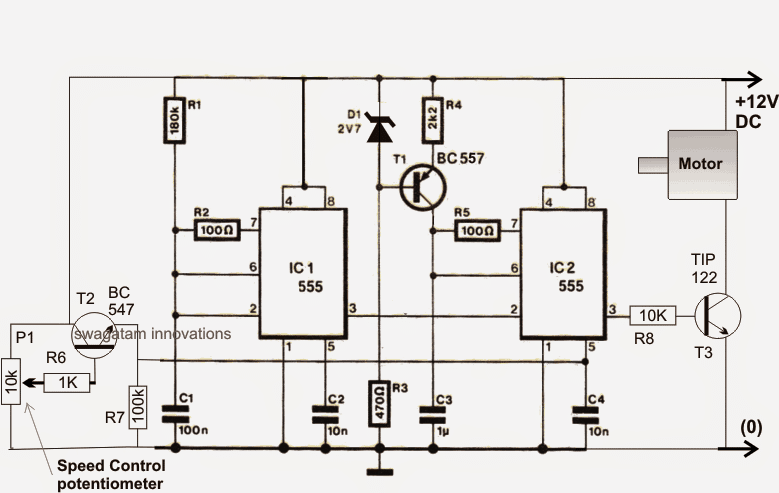
A novel 12 V PWM fan speed control circuit is shown below, using a couple of IC 555.
Using Two IC 555 for the PWM Fan Control
IC1 is used for generating a 80 Hz square wave frequency which is applied at pin2 of IC2 arranged as a PWM generator. IC2 generates a variable PWM at its pin3 by first converting the pin2 square wave input into triangle waves across C3 and then by comparing it with the voltage level applied at its pin5.
The pin5 voltage which is manually selectable or adjustable via pot determines the duty cycle of the PWMs which in turn determines the connected fan speed accordingly.
The variable voltage or the adjustable PWM pot is formed by P1, along with T2 rigged in the common collector mode.
The above explained fan speed controller needs to be powered through an uninterruptible power supply system from a standby well-recharged battery back up stage.
The battery in turn requires an automatic battery charger circuit so that it stays ready for providing an instant uninterrupted power to the fan, ensuring a smooth and a continuous supply to the motor and feed of air to the biomass cook stove.
Using Opmap Based Automatic Battery Charger Circuit
All these conditions are fulfilled in the following circuit diagram which is an opamp based automatic battery charger circuit.
The charger circuit as shown below employs a couple of opamps for the required detection and cut-off during the battery full and battery low level thresholds.
The 10k preset connected at pin3 of the left 741 IC is set such that whenever the battery reaches the full charge level the output of the IC just goes high deactivating the relevant TIP127, cutting off the charging voltage to the battery.
The glowing LED indicates charging ON situation of the battery and vice versa.
The right hand side IC 741 stage is positioned for monitoring the low voltage condition of the battery. When it reaches the lower threshold, pin2 of the IC becomes lower than the reference pin3, which in turn causes the output of the IC to go high deactivating the attached TIP127.
The load now is inhibited from getting any power from the battery.This threshold cut off is set by adjusting the 10k preset at pin2 of the IC
Here too the base LED indicates the relevant situations, glow indicates battery low, while shut-off indicates battery above the lower threshold.
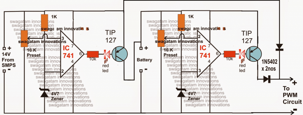
Why the Two Diodes are Used
The two diodes are connected with a specific purpose, while the mains is present the 14V supply from the SMPS being slightly higher than battery voltage keeps the horizontal diode reverse biased and allows only the SMPS voltage to reach the load or the fan blower via the vertical 1N5402 diode.
In case when mains voltage fails, the horizontal diode connected at the collector of the right hand side TIP127 quickly gets forward biased replacing the dead SMPS supply with the battery supply, ensuring an uninterrupted flow of the supply to the fan.
The 14V transformerless SMPS could be bought ready made from the market or built personally. A few suitable circuits may be seen in the following links:
12 V SMPS using TNY tiny switch IC
All the above models will need to be tweaked at their output stages for acquiring the required 14 V.


Comments
That’s really helpful to me to a great extent.
Can you please point me to a commercial ready-made controller available for purchase online? I am also here for the same purpose, looking for a ready-made controller to power biomass stove which takes two 12v fans and the setup is identical.
I am glad you liked my site, however I am sorry I have no knowledge regarding any commercial manufacturer in this field….
Sir, I am back again. I need your help urgently. I need a forward/reverse bias diode that can handle 19amp, 27v dc motor. 1N5402 could not do it.kindly list two or three such diodes. I used relay to replace the vertical and horizontal 1N5402 but it was frustrating. Thanks.
Afam, if the load is 19amp then I think the back emf would also be close to this value, in that case you would require a 20amp diode across it…Google 20amp diode you'll be able to find the options, or may be you can try a high value capacitor instead.
Hello Swagatam. I was happy when i saw the second circuit. I have done it and it is working well only that I modified it to work on 36v dc that consumes current. I replaced the 1N5402 diodes with a shockey diode that have 15 amp input but it always gets hot and burn. I was thinking if it will be replaced with a 12v 40amp relay. connect the horizontal line to N/O and vertical line to N/C. I need your suggestion or the better way to go about it. I will collect the relay supply from the pin7 of the first IC.
Hello afam,
yes you can use a relay at the output for the controlling, however 36V is too high for the IC741, you will need to drop it to 12V with a 7812 IC for feeding the pin7 of the 741 ICs otherwise these will instantly fry and stop working