In this post I will show how to construct a general purpose password based electronic lock circuit without any involvement of microcontroller. You can use this circuit for numerous applications where a basic level of security is required for turning a circuit ON.
The proposed project is built using an IC 4017 and the circuit requires a 5 digit pin number. The relay gets activated when you enter the correct pin and the relay gets deactivated when you press the reset button or turn off the circuit.
Circuit diagram:
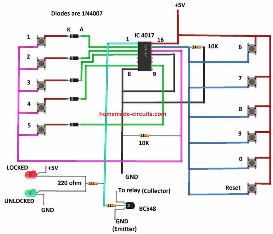
Default Password: 21345
Circuit Description:
The proposed electronic lock circuit consists of just few components; an IC 4017 which is the heart of the circuit, 11 push buttons for entering the pin number, 5 diodes to prevent short-circuit between output pins, couple of LEDs for indicating the status whether the circuit is locked or unlocked, couple of pull-down resistors, couple of current limiting resistors and a low power NPN transistor for triggering the 5V relay. The whole circuit operates on 5V supply.
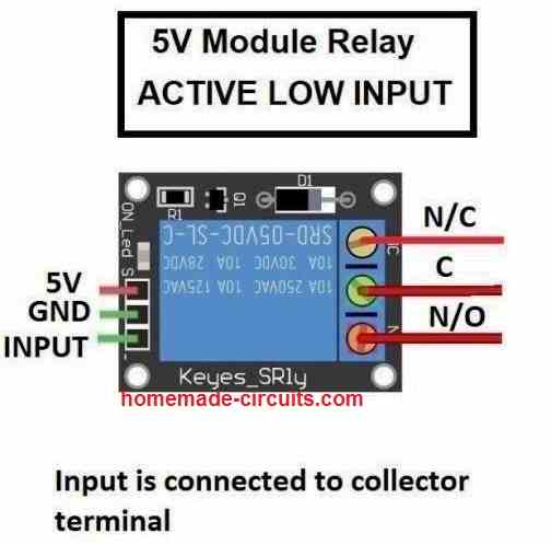
The relay we are going to use in the circuit comes in a breakout board and the input of the relay is active low, meaning if we apply GND signal to the input terminal the relay gets activated.
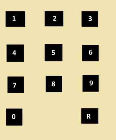
Keypad layout:
How the circuit works:
To understand how the circuit functions, we need to know the pin configuration of IC 4017 and how the IC functions:
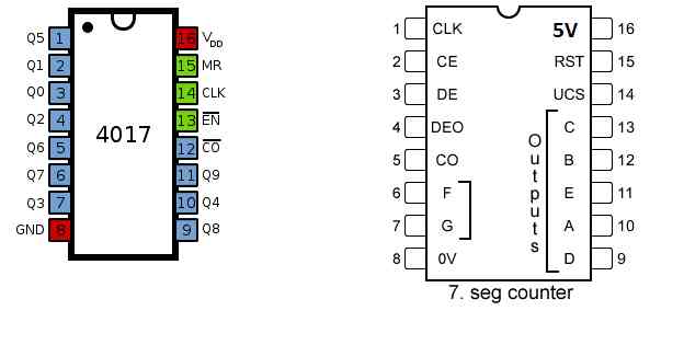
- Pin 16: Vdd or 5V.
- Pin 8: GND.
- Pin 15: Reset pin, during normal operation the pin must be grounded, when this pin connected to high the count of the IC will get reset.
- Pin 14: Clock input – we need to apply a clock pulse to this pin to make the IC count from 0 to 9.
- Pin 13: Clock enable – when this pin is connected to ground, the clock pin #14 accepts clock signal. When pin #13 is connected to high, the clock pulse applied on pin #14 gets ignored by the IC.
- Pin 12: Carry out – This pin is used for cascading two or more IC 4017, this pin turns high if the count of the IC exceeds 9.
- Pins 1 to 7 and 9 to 11 are outputs: There are 10 output pins which turn high one by one sequentially (reset of the output stays low). When no clock pulse is applied initially, output Q0 will stay high, when you apply one clock pulse, output Q1 turns high and output Q0 turns low. When you apply another clock pulse Q2 turns high and Q1 turns low. This is true for outputs from Q0 to Q9 and repeats.
- The output from Q0 to Q9 is in the sequence (pin number): 3, 2, 4, 7, 10, 1, 5, 6, 9 and 11 respectively.
By now you should have some understanding how IC 4017 functions, now let’s see how the sequential output can be developed into an electronic password lock circuit.
- When the circuit is turned ON, the output pin #3 (Q0) will be high initially. When we press the button connected at pin #3 which is the first digit of the password, sends a high signal to clock pin #14.
- Once the high signal reaches pin #14, the output Q0 – pin #3 turns low and output Q1 – pin #2 turns high, now we need to press the 2nd digit of the password, which is the button connected to pin #2.
- As soon as you press the button at pin #2, high signal reaches the clock pin, which makes output Q1 – pin #2 low and Q2 – pin #4 high.
- The above mentioned process continues till output Q4 – pin #10 turns high. When you press the button connected to pin #10, which is the last digit of your password, the output Q5 – pin #1 turns high which turns on the transistor and triggers the relay ON.
The above mentioned process works only if the correct buttons are pressed in the correct sequence, otherwise the relay will not turn ON.
In the circuit diagram all the buttons present at the left hand side are real where we need to enter the correct pin number. The buttons present at the right hand side are decoys and are electrically connected to reset pin.
When an unauthorized person tries to guess the password there is a very high probability that he / she may press one of the decoy buttons while guessing which will reset the IC.
In conclusion there are two layers of security, the first one is password that must be entered in the correct sequence only then the relay gets activated, the other layer is decoy buttons.
Even when someone is able to guess the first few numbers correctly, pressing any one decoy button will reset the IC which makes the first few correct pin numbers useless.
How to set a new password / change password:
To change the password, you need to make changes to your circuit setup physically, since there no involvement of microcontroller or software.
The default password is “21345” only if you match the push button’s number on the circuit diagram with the keypad layout’s number.
You can rearrange the wiring of the buttons at pin numbers 3, 2, 4, 7 and 10 of IC 4017 and don’t change the number order on the keypad which is illustrated on the keypad layout diagram.
- Pin number 3 is your 1st digit.
- Pin number 2 is your 2nd digit.
- Pin number 4 is your 3rd digit.
- Pin number 7 is your 4th digit.
- Pin number 10 is your 5th digit.
Note: Use button “R” (Reset) for deactivating the relay or to re-enter the password in case you entered an incorrect password.


Comments
My circuit does not work.(I excluded the relay and attached a LED with a 330R resistor to the collector of the transistor and the other pin to VCC).
The circuit was tested successfully by the author who is himself an electronic engineer, so the circuit should work if built correctly and tested step wise…
Hello, I set up this circuit and it did not work… Which model of the CI 4017 was used?
Hi, It should work because it is very straightforward circuit which uses a single 4017 IC.
Any 4017 IC should work, the type is not critical.
please replace the IC, and If you still have problems let me know I will try to investigate more…
i’ve already changed the CI but the circuit turns on direct when energized. I tested with the CI CD4017BCN and HCF4017BE
Ok, please connect a 0.22uF or any other small value capacitor between pin#15 and pin#16 and test the results, and let me know…
I did that and it’s still the same thing, so energized already triggers the rele, and the leds, and the button sequence doesn’t work. You can confirm for me the link of the relay, I do not know if it changes anything
When you first switch ON power, the relay must not energize because the relay transistor base is connected with pin#1 of the IC 4017, and when power is switched ON, pin#1 will be logic zero (0V), so the base of the relay transistor will have zero voltage so the transistor and the relay will remain turned OFF.
When power is switched ON, the initial logic high will appear and start from pin#3 of the IC 4017, and during this all the other pinouts will have 0V at their outputs….this logic high will shift from one pinout to the other only when the relevant buttons are pressed sequentially.
Please confirm and check the above first.
Are you using a relay module as shown in the above article, or are you using a discrete relay, if you are using a separate discrete relay then please make sure to add a 1N4007 diode across the relay coil.
wow ???? I have not see this b4 does it work
I have all the components
lemme try
Sure, it will work, you can try it…
if I should use 12v hope it won’t affect anything
I cannot see any reason why it cannot work with 12V, the relay will need to be a 12V type also and the LED resistors will need to be modified accordingly.
thanks ????
Sir, is it possible to latch the relay
Relay will be latched until it is reset again.
Thanks for this valuable page.In relation with the sound key board circuit, how can the key holder whistle sound decoder circuit be made.kindly explain the principle also.I would be glad to learn.secondly is there any application that you have for quick access of your circuit 555 and 4017 ICs.
Thank you! I am not sure what you meant by sound keyboard circuit, please clarify!
You can search 555 or 4017 in the search box above and find numerous application circuits related to these ICs.
Good day Sir, is it possible to design circuit that uses one code once and can never be reused again.
Hi Seun, I don’t think that’s a feasible thing which can be implemented. By the way whether a code is required to be used twice or not depends on the designer of the circuit. If the designer doesn’t want he would never assign a code twice.
Thanks Swag, how can I use MOSFET instead of relay?
No problem Seun, yes you can replace the BC548 with a mosfet.
Hello, please how can I configure this password circuit to have about 100times passcodes.
Can it work with IR and a number based remote control. Thanks
Hi, sorry, I do not seem to have the answers for your questions. Hope somebody else will be able to help you to solve your queries.
Hi: I enjoy this site, it is very interesting and very well structured and understandable. there must be many who are happy with these pages where everything is explained and almost cut out of cardboard.
it as I could think there should be a little more of PCB as I myself make printing it easier and look nicer when done, but you have many good posts.
Sincerely. Mogens
Thank you very much, and glad you liked the site!
I understand that PCB design is crucial for any project, however designing PCB consumes a lot of time, and due to lack of time it mostly becomes difficult to provide PCB layouts for each of the projects.
very useful circuit for electronics lover
thanks sir
You are welcome Balbir!