The DB9 to OBD-II adapter cable is an easy to use adapter that enables the EasySYNC range of CANbus products to fit compatibly with OBD-II interface connectors, typically utilized in automotive diagnostics.
The DB9 pinouts directly fit into the EasySYNC CANPlus modules or any CANbus adapter which complies with the CAN-in-Automation (CiA) DS102-2 pin-out.
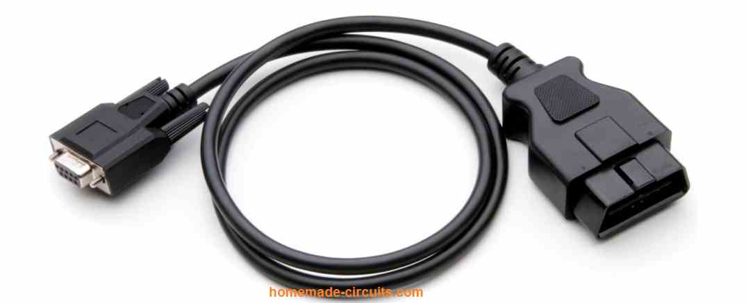
The OBD-II end can be directly plugged into any automotive diagnostic port. The cable specifically works with the CANbus portion of the OBD-II standards.
The Cable comes with a regular DB9 Female connector along with an OBD 16 Pin Male connector for executing the necessary communications across the EasySYNC CANbus products and OBD-II interface.
Understanding the Block Diagram
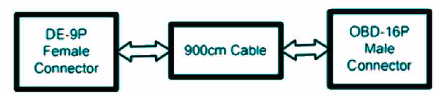
DB9 Connector (Female)
The DB9 connector is a female 9-way D-sub connector (also known as DE-9S) which can be wired directly fit with the EasySYNC CANPlus products. The signals transmitted from CANbus also comply with the standards of the CAN-in-Automation (CiA) DS102-2 pin-out.
Cable Length
The OBD-M-DB9-ES cord is 900mm long.
ODB-16P Connector (Male)
The wiring of the ODB-16P connector is designed such that it connects to the CANbus pins in an OBD-II automotive application.
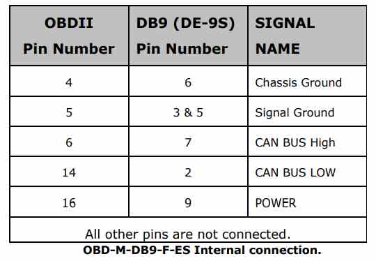
Internal Connection
The following table below indicates how the wiring of the OBD-M-DB9-F-ES is implemented.
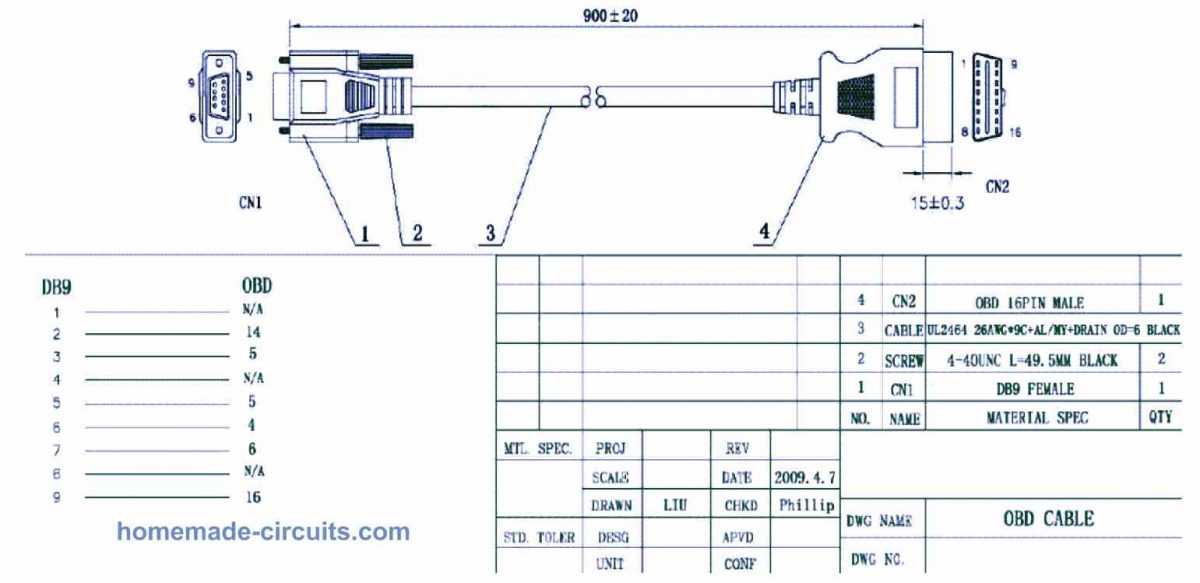
Pinout Diagram of OBD-II adapter cable
Safety Definition
The OBD-M-DB9-F-ES is specified within the Limited Power Supply (LPS) device category, designed to operate with voltages below 60VDC.
Environmental Specs
The OBD-M-DB9-F-ES is a lead-free product which conforms to the below given standard environmental guidlines:
RoHS, WEEE, REACH, PFOS and DecaBDE.


Comments
I am looking for wire color to pinout for 2006 kia rio auto/ 1.6dohc base sedan obd2 connector . pins 4 and 5 are black gnd pin 16 is red power , The shell crumbled to particles in the dash , no schematic in any kia manual nor the dealership have been able to provide a color to pin diagram.
other wires are whiteish with yellow stripe , beige to yellow wire, 2 red wires with 2 different stripe colors 1 yellow the other blu, and 1 blue wire
Although not sure, you may try investigating this page for the information:
https://www.automotive-manuals.net/kia/
I have already tried this site as well as the official kia motors down loads. they do not have schematics that apply to the specific year nor doe the schematic include color of wires .
The schematic in the KIA motors manual only has 4 wires in it for the obd connector and the 2006 connector has 8 wires in it . not even the gnd or power wires match the 2006 .
I checked Google again but could not find the exact information which you are looking for, seems like the manufacturer has not uploaded the information online.
I guess you should try posting your comment here:
https://www.kia-forums.com/threads/rear-speaker-wire-colors.331642/
I am sure you might already tried searching Youtube.
I hope you find the answers soon.
Hey, hoping I could find the pin out diagram with wire colors for a 2004 Jaguar XJ8. Not much luck so far. Thanks any help is appreciated.
I found this pdf with some relevant information, though not sure if it has the required information in it:
http://www.jagrepair.com/images/Electrical/XJElectrical/2004%20MY%20XJ%20Electrical%20Guide.pdf
Hi im trying to figure out pin wise since I already have some supplies on how to adapt my obd2 male end cable to a 25 pin male dsub connector so that I can use this adapter I have that’s 25 pin dsub female on one side and obd1 ford connector on the otherwise basically allowing me to plug my obd2 tool into a 91 ford f250 wich has the obd1 port..so I need to go from obd2 male to 25 pin dsub I appreciate your help and if u know how to go from obd 2 male to obd1 gm that would be greatly appreciated also thanks…rick
Hi, although I am not entirely sure how to solve your query, I have some general suggestions which you might find helpful:
For the OBD2 to 25-pin D-sub adapter:
Identify Pins: Find a pinout diagram for both the OBD2 male connector and the 25-pin D-sub connector. This will help you match the corresponding pins between the two connectors.
Wire Connection: You will need to map the OBD2 pins to the appropriate pins on the 25-pin D-sub connector. This may require soldering or crimping wires to create the connections.
Signal Compatibility: Check the signal compatibility between the OBD2 and the older OBD1 Ford port. If there are differences in data protocols or signal voltages, you might need additional circuitry to convert signals appropriately.
For the OBD2 to OBD1 GM adapter:
Adapting from OBD2 to OBD1 can be more complex due to differences in communication protocols and pin assignments. It may not be a straightforward process and might require additional circuitry or conversion.
Is there an adapter that allows use of arinc 429 to canbus, in & out?
Sorry, no ideas about it!
Is there a software to connect via PC?
Sorry I have no idea about it!
Thank you for your fast response