In this post I have explained a relay cut-off circuit which may be included in inverters to ensures that under a no load at the output the condition is quickly detected and the supply cut off, preventing the inverter from operating unnecessarily. The idea was requested by Mr. Rajath.
Technical Specifications
I need to adopt a no load auto cutoff system into my inverter, do you have any suitable design, which could help me. or else can you give any idea on how to achieve ,as i need to shut down the output of the inverter when ever there is no current drawn from it. please help me ,here.
Regards Rajath
The Design
In a few of ay previous posts we have learned how to make overload cut off circuit such as:
Low Battery Cut-off and Overload Protection Circuit.
Motor over current protector circuit
However, the present concept deals with an opposite situation wherein a no load condition is supposed to be detected and cut off for persisting, that is I have explained a circuit for preventing a no load condition for inverters.
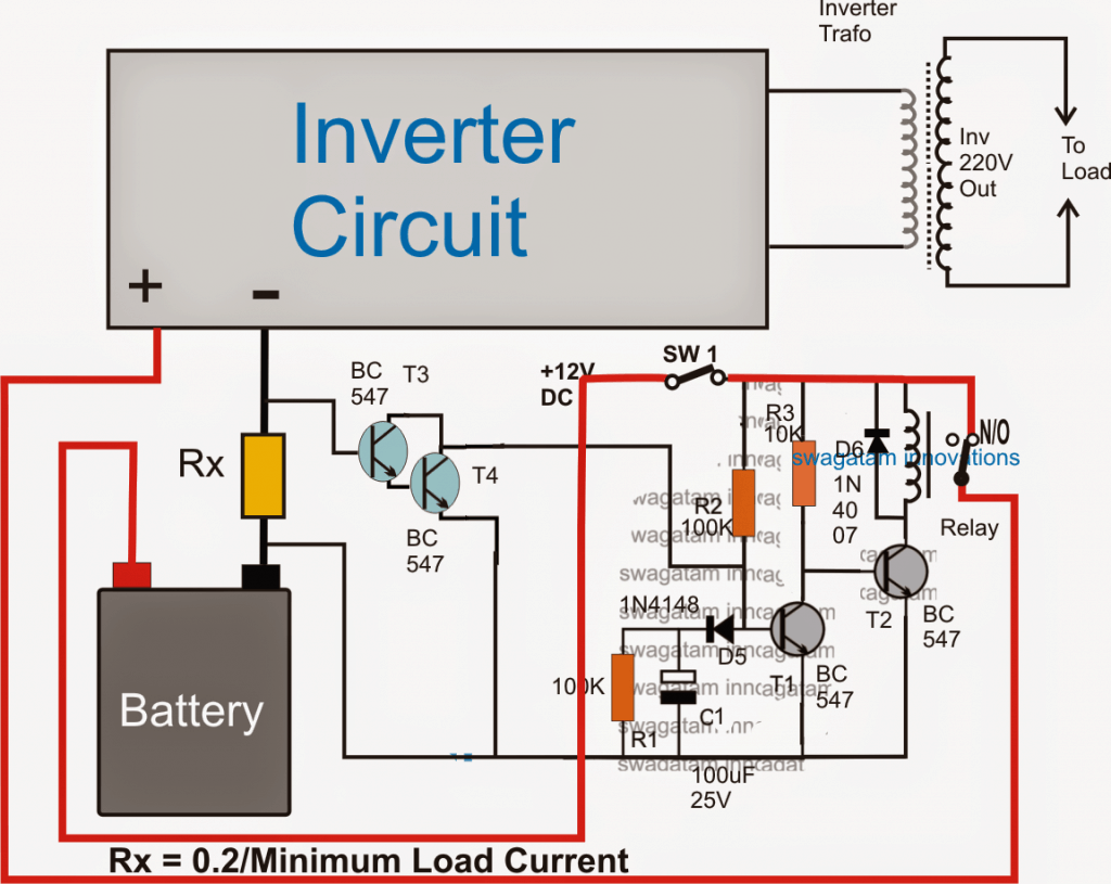
As shown in the above figure, a no load detector and cut of procedure can be initiated by incorporating this design in any inverter circuit.
The operational details may be understood with the following explanation:
The circuit comprises two stage, namely the current amplifier and sensor stage using the T3/T4 Darlington pair, and a simple delay ON stage using T1, T2 and the associated components.
As soon SW1 is switched ON, the delay-ON timer counting is initiated through C1 which begins charging via R2 and D5 keeping T1 switched off in the process. With T1 switched T2 is switched ON which in turn switches ON the relay.
The relay enables the positive from the battery to get connected with the inverter so that the inverter is able to start and generate the required AC mains to the intended appliances.
With the presence of a load at the output the battery undergoes a proportionate amount current consumption, and in the course Rx experiences a current flow through it.
This current is transformed into a proportionate amount of voltage across Rx which is sensed by the T3/T4 Darlington pair and it is forced to switch ON.
With T3/T4 switched ON, C1 is instantly inhibited from getting charged, which leads to an immediate disabling of the delay ON timer, making sure that the output of the inverter continues to supply the voltage to the load.
However, suppose the output of the inverter is devoid of any load (no load condition), T3/T4 is then unable to switch ON, which allows C1 to get charged gradually until the potential across it becomes sufficient to trigger T1.
Once T1 is triggered, T2 is cut off and so is the relay. With the relay contacts cut off and shifted from N/O to the N/C contact, the positive to the inverter is also cut off, the system comes to a stand still.


Comments
I have a charger which has a current cutoff that is too low, and doesnt have a pot inside to adjust it higher.
Could this be adapted for that?
Could RX be replaced with a potentiometer?
Would a relay be too electrically noisy and interfere with the BMS and/or charger?
Charging load = >84v 10.5A max
Thanks
Yes, that’s possible, but the variable current configuration must be done through a parallel preset, as shown in the following figure. The relay operation will not be noisy, if you put a snubber network around its contacts, and also put a 100uF capacitor parallel to the coil of the relay:
https://www.homemade-circuits.com/wp-content/uploads/2025/07/current-sensing-adjustable.jpg
How does the 1k pot affect the equation for Rx and wattage?
Will it give me a .2 – 1A range?
Obviously the relay will have to be uprated for +84V but what about the other components? ie BC547 max voltage is 45V
Could the turn on phase confuse the CC/CV charger?
The Rx wattage has no relation to the 1k preset.
for 1A current, Rx = 0.2/1 = 0.2 Ohms
wattage = 0.2 watts.
For the relay you can use a 12V relay with a buck converter regulator such as the one explained in the following article.
I have no idea about your last question.
https://www.homemade-circuits.com/adjustable-1-2v-to100v-dc-buck-converter-circuit-using-lm5164/
if the load current is say 10am,what will be the wire gauge from the base of t3/t4 and the +terminals of the base? I am really confuse sir
wire gauge is not important for T3/T4 base….it can be any thin wire.
Please can you assist me with 24volt 2kva inverter circuit with full protection?
you can try the first diagram from the following article:
https://www.homemade-circuits.com/inverter-circuit-with-feedback-control/
First try this basic diagram, if you succeed then you can upgrade this to 2kva
Hello, thank you for your diagram, it is very enriching. I would like to use it to automatically turn off a solar inverter when not in use (no load). Do I have to choose a high-current relay if I plan to draw about 100A from the battery when the inverter is on? Thank you in advance
Thank you, yes the relay contact current rating should be ideally two times more than the intended maximum load current
hello sir
i try this circuit but when i disceonect the load and connect it again the relay dosnt switsh on
The load should be high enough to create at least 1 V across Rx and enable T3/T4 conduction. If this does not happen, the relay will not activate
Hello Sir
-The battery is a12V 8Ah lithium ion
-The inverter is 12 TO 220V based on transistor astable 60Hz circuit with 2 irf640 mosfet connected to 300 watt center tape toroidal transformer
-The minimum load is 220V 9W bulbs consuming 0.340 A
-The system consume 0.16A with no load connected
-The system consume in total with the bulb connected 0.5 A
+what i need :
-The relay to switch on every time i switch on the bulb
-The relay to switch off every time i switch off the bulb
How i can make the circuit work with this system ?
Hello sir pliz help me build a1500watts inverter,I have no idea on how to make one, pliz show me the simplest circuit
Hello Godfrey, you can select any inverter circuit presented in this website and replace the MOSFETs with two parallel IRF540 for each channel. For battery use a 24 V 300 Ah battery, make sure to operate the oscillator circuit through a 7812 IC, and replace the transformer with a 24-0-24v, 70 amp transformer
Hi,
I think for battery-powered applications relays are not a good choice, because of high coil current when energized. Can you suggest a good efficient replacement?. My considerations are p-channel power MOSFET or solid-state relays.
Thanks
Nikhil
Hi, a relay is much better since it will allow the inverter to work with 100% battery power. The coil consumption will be negligible, may be 1 or 2% of the total inverter consumption. A MOSFET or SSR will dissipate energy causing the inverter to work with lower efficiency.
Thank you, sir, for the reply.
I have one more doubt.
There is a chance for a slight increase in the voltage of a battery when a load is disconnected from the battery. Due to this, there is a chance for the relay to switch on again if the no-load battery voltage is above cut-off voltage. So a couple of switchings will occur before a stable state is reached.
Is this possible ?.
if possible, then how to solve this?.
Thanks & regards,
Nikhil
Thanks Nikhil, The circuit is not voltage dependent, it’s current dependent. Voltage fluctuations will not affect the relay circuit, its the load current that will affect the circuit.
Because there has no center tape transformer will be used for output supply
You can try this:
https://www.homemade-circuits.com/2014/01/simplest-full-bridge-inverter-circuit.html
This is the only recommended design
ok Sir i will let u now when i am done
CORRECTIONS
Rx=0.2/0.4(400mA) =0.5ohm
hence 0.2x5A=1watt
therefore Rx=0.5 ohm 1 watt
did i do it correct??
yes that looks OK to me, use a wirewound type resistor preferably.
That mean 0.5x5A=2.5 watt, therefore =0.5ohm 2.5watt resistor?? OR
0.5x 10A=5 watt, therefore =0.5ohm 2 watt resistor??
It is not 0.5V it is 0.2 or 0.3V, please check again….
ok sir as i did calculate it here
0.2/0.2=1ohm resisor,
0.2x.0.2=0.04 watt
That mean my resistor current must be 0.04watt am i correct???
it should be:
Rx = 0.2/0.4 (400 mAmps) = 0.5 ohms
wattage = 0.2 ohms x inverter maximum current.
inverter maximum current could be 5 amps or 10 amps as per inverter wattage
GOOD MORNING SIR, i hv made this circuit today but the problem is that the Rx resistor is burning why?? it is 1 ohm 1/4w Check the image here
https://mobile.facebook.com/photo.php?fbid=1835553799874433&id=100002594924040&set=p.1835553799874433&source=47&ref=opera_speed_dial_freefb&__tn__=R
The formula for wattage will be: voltage drop across the resistor multiplied by the maximum current rating from the inverter battery.
Here the voltage across the resistor is supposed to be 0.2 or 0.3V, so multiply this by the maximum current draw of the inverter…..that will give you the wattage of the resistor.
thank u sir
sir if i got you right that mean if my threshold is 400mA that mean i should calculate the Rx like this:- 0.2/0.2=1ohm resisor,
0.2x.0.2=0.04 watt
It should be Rx = 0.2/0.4 = 0.5 ohms, in this case if the load is consuming below 400mA, the relay will switch OFF the inverter
Sir
I need to construct the circuit to store combined electricity from solar and piezoelectric in battery and this battery will be used for inverter input .
It can be possible sir?
Swapnil, how much voltage and current are you getting from your piezo source???
Doesn’t make sense. Even if the inverter is off you are losing the power at Rx resister
“losing power at Rx?” How? if the relay is switched OFF how will the inverter consume power??
Hello Swagatam,
Everything is 100% clear now!
Thanks a ton for your time and dedication to explain the formula in detail.
Very much appreciated!
Success and regards,
Rick
You are most welcome Rick!!
sorry, the answer should be 0.02 watts
…however 0.1 amps cannot be considered for calculating the Rx wattage, because 0.1 is the minimum current value, we would want it to be multiplied with the max current limit, which could be say for example 2 amps.
so Rx wattage for this example would be 0.2 x 2 = 0.4 watts
for example let's assume the current threshold to be 100mA
T3/T4 triggering potential to be 0.2V, the Rx will be
0.2/0.1 = 2 ohm
wattage will be 0.2 x 0.1 = 0.04 watts
Hi Rick,
the formula for calculating RX is T3/T4 minimum triggering level divided by the desired current threshold, and the wattage will be the desired current threshold multiplied by the triggering level.
I hope you got the relationship
Hi Swagatam,
Trying my luck again…
Ohms value calculation of Rx is clear, but what about Watts?
Thanks for your help,
Rick
Hi Rick, I have clarified it in the above comment….
Thank you for your reply. Do you sell parts? If not, do you have a parts list?
sorry I don't sell parts
the parts are already specified in the diagram, please click to enlarge it, and copy down the numbers as mentioned in the diagram…all the parts are standard type and does not need any consideration.
Hi, I came across this post and the concept of your circuit is exactly what I am looking for. I have a 4k 110v AC inverter powered by 4 6v batteries wired in series for 12v. The inverter has a power saver mode built in (25 watts) but it will sense and turn on my 110v AC refrigerator. However, when I open the door, the light bulb is enough to trigger the inverter to power on. Also, the power sensor pulses every 3 seconds which I'm afraid might damage the compressor. So my question is, is the load in your circuit adjustable and how would I do that to sense a low load. Thank you in advance for your reply.
Hi, the resistor Rx value can be altered as per the required specifications, and the inverter can be enabled to switched ON or OFF at any desired load conditions. Higher values will allow the inverter to operate with higher loads only and vice versa,
hellow sir i have this 60watts inverter what will be the value of Rx at full load and how can i obtain this minimum load current?
hello Bady, you can use the same value that's indicated in the diagram.