To make this simple MPPT circuit we first modify a standard LM317 power supply circuit into a buck converter then configure it with a solar panel for implementing an MPPT function.
Modifying a LM317 Power Supply into an MPPT Solar Optimizer
In our previous article I have explained how a standard LM317 power supply could be transformed into an inductor based efficient variable buck converter power supply circuit.
In this article we analyze how the same circuit design could be enhanced into an effective MPPT circuit by a adding an LDR/LED optocoupler and an opamp voltage follower circuit stages.
The complete circuit diagram of the proposed MPPT circuit using LM317 buck converter can be witnessed in the following image:
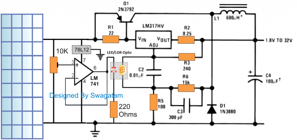
The figure illustrates the discussed MPPT circuit, the LM317 and its associated components form a basic buck converter circuit whose output can be varied by simply varying a resistor across C2.
In our previous power supply design we saw a pot being positioned in parallel with C2 for enabling the variable output voltage feature, however since the present design is supposed to perform an automatic MPPT, this pot could be seen replaced with an LDR/LED opto coupler.
How the Circuits Works
The LED LDR opto coupler is a simple homemade device wherein a red LED and LDR are sealed face to face inside a tiny light proof enclosure.
The LDR leads here can be seen connected in parallel with C2,while the LED is integrated with the output of an opamp voltage follower circuit stage.
The input of the opamp can be seen hooked up with the solar panel through a 10k preset.
The idea here is to make sure that as the solar panel voltage increases, the opto LED intensity also increases, which in turn causes the resistance of the LDR to drop.
The dropping resistance causes the buck PWM is narrow its pulses thereby preventing the output voltage to rise, but nevertheless ensuring a proportionate rise in current for the connected load.
In one of my earlier post we understood that in any buck converter design the output from the converter depends on the PWM and the input voltage.
That implies if the solar voltage tends to increase, the buck output could get affected and begin increasing proportionately. This could in turn cause overloading of the panel and degrade the efficiency of the panel.
The present LM317 MPPT design takes care of this situation through the LED/LDR device and the LM317 variable resistor feature, and combines the two features in conjunction with an opamp voltage follower to develop an effective self adjusting PWM based MPPT circuit.
The adjustment of the opamp 10k preset appears to be quite simple.
How to Adjust the LM317 MPPT Preset
At optimal sunlight, the 10k preset is adjusted such that the output from the buck converter produces a voltage on par with the load voltage specification.
For example suppose the load is a 12v battery, in that case the 10K preset is adjusted to produce around 14.4V.
Once this is done, from here on the output could be assumed to self adjust in response to the sun shine...meaning now as the sun shine increases the LM317 buck converter self adjusts and narrows the PWM at the base of Q1 inhibiting any rise in voltage, but in the process the inductor L1 and C4 makes sure that the excess sunshine is transformed into a proportionate amount of extra current for the battery to enable a faster charging.
Conversely if the sun shine deteriorates, the PWM tends to widen, causing the voltage for the battery to self adjust automatically maintaining the 14,4V level...... albeit with a proportionate amount of reduction in the current.
The self optimizing functionality is carried out throughout the day ensuring the most effective outcome from the panel for the connected load.
WARNING: THE ABOVE EXPLAINED SIMPLE MPPT CIRCUIT USING LM317 IS BASED ON THE AUTHOR'S ASSUMPTION AND SIMULATION, VIEWERS ARE ADVISED TO ASSESS THE CONCEPT THOROUGHLY BEFORE ATTEMPTING IT PRACTICALLY.


Questions & Answers
amazing,, im thinkin` same ckt before the last time youve shown the LM317 as BuckConv, very impressive.. thanks author & Sir/Engr Swag(Hitman). The cheapest way to have MPPT alternative, how cool!
you are most welcome grayback, I am glad you liked it!!
Pls is this. Circuit tested n can I use it for my 40watts solr pannel and what's the maximum amps of battery it can charge
you can use it with a 40 watt panel. the circuit can be upgraded to charge any battery simply by modifying the L1 and Q1 accordingly
sir how may i reduce 12v battery to 9v
you can use 4 series diodes with its positive line.
How can I use it for 200w ,250w,300w 24v or 12
by proportionally increasing the ratings of Q1, R2 and L1
Hello Swag, you said for higher panel rating 250w just change Q, L , R2 but the maximum output current for lm317 is 1.5A. Please how is this compatible with high panel wattage
Hello Glory, the IC LM317 is used only for implementing the buck converter circuit, the output current is controlled by the PNP, therefore the PNP becomes solely responsible for the output current delivery.
what is the replacement of BJT 2N3792
TIP32 or BD140
Can I use tip147 transistor
yes you can use it for Q1
Thanks so much. it’s working great, but the tip147 is getting too hot at high current gain.please how can I combine it in parallel. Thanks once again
Glad it’s working Glory, TIP147 can handle upto 10 amps, but transistors can begin heating even when only 20% of the rated current is applied across them, so a large heatsnk becomes essential for these devices.
If you want to put them in parallel you can simply join their respective terminals in parallel, but make sure to mount all of them over a common heatsink.
https://www.homemade-circuits.com/transistor-facts/
Thanks sir for your response, I think I got a wrong result earlier, where I said I had current gain from the mppt design, I am getting the following result presently.
At 2.02pm weather partly cloudy, I measured the Solar voltage without any connection, I got 18.53v
Pwm-1.74A the controller I bought
Mppt -1.46A. I Set the output voltage at 14.4v
Please why could this be, what can I do. Thanks
Hi Glory, which MPPT are you referring to, is it the above one?
The above design is totally dependent on the optimization of the coil parameters and the frequency, its performance can be improved by experimenting and optimizing these parameters to the most effective levels.
To optimise the frequency how do I change the capacitor, with c2 of 0.01uf I got frequency of 155hz. What should be the range of frequency to get optimum result.thanks.
C2 is not responsible for the frequency change, it is R6/C3 which determine the frequency range, you can read more on this here:
https://www.homemade-circuits.com/lm317-variable-switch-mode-power-supply/
Thanks, can I use tip122 instead, I don’t have have tip 147 for now
sorry, TIP122 is an NPN so it won’t work for Q1
Thanks so much for your educative site and well organised system. This is the comparison result BTW my bought pwm charger and the built mppt.
Presently the weather is cloudy @Vin-19.12V
Pwm- Iin- 2.79Amps, Iout-2.52Amps
Mppt-Iin-2.08Amps, Iout-2.89Amps
Please sir, I want to ask,
1. why is the Iin 2.08amps for the mppt lesser than that of the bought pwm
2. What can I do to solve this.
Thanks for the good work sir, God will bless you more and more abundantly.
Hi Glory,
where did you measure the input voltage, is it across the solar panel? But anyhow it is the output that becomes important, and since you are getting higher amps with the MPPT that looks much efficient. The drop at the input voltage could be due to the loading and switching of the inductor of the MPPT buck converter.
Please sir give me the values of the components I need to change for 24v battery load with 300w/24v panel, because I tried some changes, increasing the Q, L and R2 but the resistors are getting burnt. Thanks sir.
Glory, make sure the voltage does not exceed 25V, in this condition you can reduce the 22 ohm to 10 ohm, increase LED resistor to 1K, and reduce R2 value to 0.1 ohms. Rest can be as is.
However I am not sure about L1, you may have to experiment with it by initially trying 1000uH inductance value
Thanks sir, but the solar Vin is 38.6v, please any way around it.
OK no problem, I just forgot that the IC LM317HV is rated to handle upto 60V, just make sure Q1 is also selected appropriately
Good day sir, thanks for your update, what is the function of the voltage follower and how does it work in this circuit.
Thanks Glory, the voltage follower opamp acts as a buffer between the panel and the LDR, and helps to provide an equivalent level of supply to the LED in response to the panels varying voltage and ensures a safe operation of the LED
Good day sir, how can I improve the mppt efficiency, what are the factors I should work on, the losses are great.
Glory, the above circuit is a basic design it does not have any room for further improvements, …except the initial adjustments, and the component selections
can this circuit be dirctly connected with inverter of cd4047 (12-230v)???
No, it's only for charging a low AH battery throughout the day.
▶Sir, i need your help very badly. Cause you help others. Can i ask my question?
sir how may i reduce 12v battery to 5v 2A
you can use two 7805 ICs in parallel, just make sure to mount both on a common single heatsink.
good day sir.Im having a problem with my thesis on the solar charger circuit because i tried so charger circuits but the power drop is pretty big.My solar panel’s current output is 1.1amps and when it goes to the charger circuit..the output becomes 100milliamps..Can you give me a 24volts solar charger circuit sir with less power loss.
Hi Michael, which charger circuit did you use?
and please provide the voltage specs of your solar panel also
i’ve used your automatic charger regulator using lm338 with comaparator lm 741 and voltage regulator 78L12..for all the resistors in your design,i choose their power at 1watt..At that time its not the sunny but i’ve series a 2 pcs 12volts 20watts solar panel to add their voltages.the resulting output voltage on the solar panel was 15 volts but when i tap in on the charger that i made..The resulting output of the charger that i’ve measured was 3.43 volts and then when i measure the current with my multimeter.It was 17.56milliamps only.Can you give me a advice if what should i do?may battery is 12volts7ah and my thesis proposal was 24volts input in the buckboost converter that will give an output of 0 to 48 volts dc..Please help me on this sir..Thanks a lot
my plan is to series a 2 pcs 12 volts battery so that it will result a 24 volts dc output sir.So that’s why i’d like to ask a help from you if you have a 24 volts solar charger circuit with less power loss.I think the comparator and regulator consume so much power that’s why a big power loss resulted on my solar charger.Sorry for my bad grammar because its already midnight here and i’m so sleepy right now.
Nope!, that’s not correct, the LM338 will consume some power but it will still provide a good output, if you are getting 3V from 15V input you have definitely done something seriously wrong in your circuit.
alternatively you can try the following one
https://www.homemade-circuits.com/lm317-variable-switch-mode-power-supply/
but I doubt, if you could not make a simple LM338 circuit then the above can be even more difficult for you….
you mean to say your LM338 IC regulator give 3.43V when a 15V is applied at the input? that’s not possible unless you have done some mistake in the LM338 circuit. How did you adjust the LM338 pot? even a 7812 will give you a clean 12V with a 15V input.
also without sunlight the panel current will be quite minimal, so make sure to check the panel current first before connecting to the LM38 circuit.
first confirm the LM338 output, after that you can go ahead with the controller cut off setting…do the procedures step-wise.
Hello, you can post the editing of the circuit for the PV panel with the following data: Pmp 200Wp, Vmp 78.3V, Imp 2.55A, Voc 99.7V
dear sir,
what are the values of resistances R1, R2, R3 and R5?
they are all in Ohms!
Hi sir,
I’m using your lm317 mppt design for an academic research and need an assistance on components selection with mathematical backups.
Hi thakib, you can refer to the datasheet of the IC LM317C you may find the technical details there, beyond this I do not have any further data.
Good day sir, please what’s the diff between the above circuit and 555based buck converter circuit for mppt, thanks
Tolu, both are based on same principle and might work identically.
Good evening sir. According to the circuit diagram, i got to know that the circuit can provide an output voltage of 1.8-32 V. Can i get to know the specifications of the solar panel to be used for the proper working of the circuit. I mean to say that what is the range of input voltage and current this circuit can handle.
Please do reply sir.
Hi Ashish, The range of the solar panel can be between 8V and 35V, current will depend on the rating of Q1.
Hi
I am looking for a Proteus Project File on Micro controller MPPT circuit.
Sorry, I do not have it with me at this moment!!
Very interesting, helping, impressive website. I,m very happy sir. Please keep it up.
You are welcome Sageer!
Hello sir, please how can I prevent high voltage going to the battery if the Q1 becomes faulty, because I noticed if the Q1 short circuit, the input voltage is same as output voltage.
2. the ideal way if to connect battery first before the panel, how can I prevent the solar controller from start charging if connected otherwise.
thanks sir
favour, you can add a fuse with the collector of Q1 to prevent an accidental short circuit.
sorry I could not understand your second point.
thanks sir, I meant how to ensure the solar controller is not damaged by high voltage input if the controller is connected to panel first before the battery,
any method to prevent such wrong accidental connection due to high solar input.
Favour, you can use a shunt regulator at the output of the solar panel, as shown in the following article:
https://www.homemade-circuits.com/solar-water-heater-with-battery-charger/
see the left side op amp circuit, this will never allow the solar panel voltage to rise above the predetermined levels.
Thanks sir, I want to ask if the circuit in the left in the link below, is connected to the solar output will not affect the mppt voltage input, I think it suppose to be connected to the mppt circuit output.
2.can the left circuit be used for float charging controller.
https://www.homemade-circuits.com/solar-water-heater-with-battery-charger/
Hi Favour, It has to be connected to the solar output so that the excess power can be shunted to ground, so the diagram is correct.
For float charge controller you will have to limit the current accordingly using a current limiter stage.
Thanks sir, please give me a good current limiter circuit.
You can limit the current through any of these circuits:
https://www.homemade-circuits.com/universal-high-watt-led-current-limiter/
Hello sir, please how can I add indicators to the circuit- charging and battery full
you will need an op amp ciruit for that
Please, is there anyway to optimise the this circuit to avoid losses because for tl494 pwm circuit components are scarce in my region . Thanks
You can search online for “12V buck converter circuit” and use it for your application.
Moving forward, I discovered the inductor has no impact in the circuit because I tested it with and without the inductor, there was no difference in the output current. Any suggestion on this
You can refer to the datasheet and check the calculations:
http://www.ti.com/lit/ds/symlink/tl494.pdf
Hey
im wondering how this sort of circuit could be designed for driving large dc automotive fans (about 30 amps draw) with an undersized solar panel. obviously running current limited to about 5 or 10 amps, what ever the solar panel can provide.
in simplifying this design i wonder if the motor itself could replace the inductor.
motors are hard because you want to both limit inrush current as well as have enough current to get them started. maybe you need to store up a pulse in a large cap then only enable the output once charged?
any thoughts would be appreciated!
there are lots of applications for this, like direct coupling solar panels to fans or pumps, where variable speed depending on the solar input is desirable.
by contrast a fixed current limiting means you need a massively oversized solar panel.
the whole point here is to avoid using batteries
cheers,
j
If the fan current rating is 30 amp and the solar panel is 10 to 15 amps, then the solar panel voltage will need to be at least 2.5 times higher than the fan voltage rating.
The inductor in the above LM317 circuit cannot be replaced with the fan.
If you want to remove the current limiting, you can simply remove the R2 resistor and replace it with a short jumper.
The PNP transistor can be upgraded to higher rating for enabling current over 30 amps…
Hi,
I am looking to find out if the transistor 2N3792 can be switched out for a MOSFET and if it is possible to convert the circuit to a buck-boost or boost circuit as I need to charge a 36V battery
Hi, it is probably possible, but the 22 ohms will need to be increased to generate an optimal 12V for the mosfet gate switching at a load of around 1 amp current…..
Hi,
What would need to be changed to convert the circuit into a buck-boost converter to charge a 36V battery
Hi, sorry, this circuit cannot be changed to a buck boost version
Dear Swag,
I have made a design of a modified sepic converter which I do intent to use as an led driver for four led corn light bulbs with the following specifications, head voltage of 359 millivolts wattage of 26 watts. The problem I do have is that I am getting power from a battery with the following specs 12 volts 76 amps. I do know the best way to drive led light bulbs is that of constant current. My question is I need a general method of stepping down high current to manageable level to suit the prevailing needs. If it were ac it would have been very easy because I can use either step down transfomer, bridge rectifiers ect.
Dear Bernard, sorry are you sure the forward voltage spec of the LED is 359 milivolta? I have never seen an LED working with such low voltage, please clarify this, I’ll try to figure out the solution…also how do you wish to connect the LEDs, in series or in parallel, I guess it is in series?
Hi Swag ,
I am 100 percent sure that the led light bulb is 359 millivolts.The wattage being 26 watts and its dimmable.I would be glad to give me a general solution as a whole in stepping down dc current to required levels.Thank you.
Hi Bernard, please give me the link of the datasheet of this LED, I’d like to see its specs. If we divide 26 with 0.359V, it gives 72 amps, so do you mean the LED requires 72 amp current to illuminate? Please check the dataseet or provide the link.
please do not put http on the link
Hi Swag
To be quite honest I bought the led lamps from a local supplier
here in Harare Zimbabwe a couple of years and never bothered to
Ask the source that is where they got them from.But its true the lamps corn lights 359 millivolts 26 watts were there its only now that they dont deal with them any more.The shop is called Amanat its a hardware shop.Any way Swag I dont want to give you a tall order.If you can give me a general idea or guide line of how to step down high current to a low one for constant current
Led drivers .I would be glad .I can forget about this one and start
On something new. Sorry for giving so much head ache on this one.
Hi Bernard, To drive an LED from a higher DC to a lower DC, you can use linear ICs like 7812, 7805, LM338…for current control you can apply the following concepts:
https://www.homemade-circuits.com/universal-high-watt-led-current-limiter/
https://www.homemade-circuits.com/simple-current-sensor-circuit-modules/
https://www.homemade-circuits.com/make-hundred-watt-led-floodlight/
https://www.homemade-circuits.com/constant-current-source/
Hi Swag,
Thank you very much for your untiring support. Truely you are a rare person to find and may god bless you in all you work.
No Problem Bernard, I am always happy to help!
Hi Swag ,
Thank once more and stay blessed
pls i have a 12v, 1200ah battery pack system
i also have 1710 wats solar system at 35v all panels connected in parallel and hopping to increase them soon.
pls could you help me design a real circuit diagram that would help me charge the battery pack most efficiently in mppt mode with the basic functions of buck, constant and float charging stages.
the display on the SOL showing the exact volt and amps from the solar side and the BAT showing the exact volt of the bat and the exact current going into it.
thank you.
NB; i understand the heat dissipation of high current in low volt systems.
Sorry that’s a lot of work, and sounds complex too, not possible for me at this moment.
Please Sir can this charge 24v. 12v battery x 2. 200Ah?
No, it is meant for 50 Ah battery maximum
Ok. I love the design. Can it be modified? What do I modify to increase the output to be able to charge it? I am curious because I have already done one but want to ask before trying. The LM741 gets really hot. what if I use LM386?
The IC 741 shouldn’t get hot if the input supply is below 24 V. You can add a 10K resistor in series with the 10k preset and check if that helps. I am not sure whether LM386 can be used as a voltage follower or not.
Lolz. My input voltage is 30v. The 10K resistor in series is a good suggestion. Thanks. What about getting a higher output current. I really want to charge my 12 x 2(24V 200ah batteries). I bought new Epever MPPT but it stuck on the way. No flight coming from China. I thought It will be good idea to use available components in my country to make something I could use for the meantime to save the batteries. Your great knowledge will be helpful. Thanks
No problem, just make sure the 10K is on the positive side of the preset. You can try the shown basic design first, if it works as per the specifications then you can try upgrading it for the 200 Ah battery.
Hello, very nice diagram.
I would like to adapt it to charge a 100Ah acid battery. I was thinking of replacing Q1 by an MJ2955 and the LM317 by an LM338 to support more current.
If what I want to do is possible then how do I calculate R2 and L1?
I also plan to add another circuit to manage the battery charging steps, do you have an idea for that please?
Hi, Charging a 100 Ah may be possible, however an MJ2955 might require a very large heatsink. The values of L1 and R2 can be as is, but the wire thickness of L1 will need to be upgraded accordingly, perhaps, a 21 SWG wire for L1 should do the job.
For the battery auto cut off, you can try applying the concepts explained in the following artile:
Op amp Battery Charger Circuit with Auto Cut Off
Hello, since the circuit is based on a LM317 then must Vin be 3V higher than Vout? If this is the case is there a way to set the output to a value.
For example if the panel voltage is 14V, I would like to have an output of 14V. And if the panel voltage is 18V, I would like to have an output of 14V but with extra current.
Hello, the 3 V differential may be true for this circuit also. So at 18V you may get the mentioned results, but at 14V you cannot get 14V, since this is a buck converter circuit, and a 3 V differential may be always required…
Hello,
Since the 3V difference is still needed here, is your MPPT circuit based on an IC555
(second diagram from the end) also requires a voltage drop?
My goal is to design an LDO MPPT circuit to charge 12V batteries (with Vfloat about 14.4V max).
The problem with the LM317 circuit is that it will only be effective in good weather conditions and if the solar panel produces 14+3V or 17V. At 14V as you say, we cannot have 14V anymore.
Hi, I would recommend the following design instead, which will adjust to the input perfectly, and make sure the output is always constant:
https://www.homemade-circuits.com/homemade-solar-mppt-circuit-maximum/
As I see, the buckconverter is exactly the one from the Texas Instruments data sheet for the LM317HV, which I think is good!
I am wondering, if one could spare the operational amplifier LM741 including its voltage regulator 78L12, the LED and the assosiated resistors, if the LDR is just presented to direct sunlight close to the solar panel. Maybe with a potentiometer parallel to the LDR to adjust the output voltage.
That may be possible, but that won’t give you the level of accuracy you can get from the shown op amp/preset setup, nonetheless it is worth trying.
Thanks,
what do you mean by accuracy? Could you please explain, what difficulties you expect?
The op amp preset can be used to create proportional amount potential ranges across the LED/LDR. For example if the solar panel output is between 0V and 24V, this can be adjusted to 0 to 12V or 0 to 5 V proportional voltage ranges by using the op amp preset….this cannot be achieved using the preset across the LDR exposed to direct sunlight.
Thank you for setting this straight.
Would you also have an example for such a MPPT adjustment in combination with a boost converter?
Glad it helped!
sorry, presently I do not have an LM317 based boost converter circuit
Can I use this circuit as a dc motor driver instead of a battery? What is the max wattage that this circuit can deliver without dammaging it?
You can use it for driving a motor also. The output wattage will depend on the current handling capacity of the PNP transistor.
I own a charmer plompbde 48v 59.3 V I would like to charge a Lifepo4 150A battery from Huawei. right now I’m charging it, with a 50 volt plonb charger. which of course is not enough, is it possible? without damage?
A 150 Ah Lifepo4 battery might require a 100 amp current to charge rapidly, which may not be possible using an LM317 IC.
How do I design this electronic circuit, and is it possible to have a simple explanation of how it works?
I have tried to explain the concept in simple words in the above article, but if you are still unsure, you can ask your specific questions, i will try to solve them for you…
I want to do a bachelor’s thesis on the MPPT device. Can you help me?
Sorry, writing a thesis may not be possible for me, you can take the help of Chat GPT for this.
Hello, I’m very intrigued by this design. Very simple and straightforward. What I would like to know is if it would be possible to use this device to connect to a bank of other solar panels and all their outputs merge into a single line and are fed into an MPPT charge controller. For instance, I have 10 solar panels that were previously used, so their outputs all vary in VoC and ISC, which also effects the Vmp/Imp as well. So I am looking for a way to take all these panels and get the most of each one and then dump that power into a common rail to send back to the MPPT Charge Controller. Would this circuit work for this type of situation? Also would it be easy to add an esp32/8266 for reporting performance of the panels output?
Hi, thanks for your interest in this circuit, however, this circuit is designed based on my assumptions only, and I am not sure if it will really fulfill the mentioned outcome or not.
If you are looking for a simple MPPT concept, I would recommend the second circuit from the following article and I am confident it will provide the intended results:
https://www.homemade-circuits.com/homemade-solar-mppt-circuit-maximum/
You can use the esp32/8266 for reporting performance of the panels output.
Hi sir, and happy new month sir,
I using a 30A PowMr mppt, with a single 24v 300w solar panels and 12v 20Ah battery, sir I wanted to know why my mppt is drawing low current max(1.1A in high sunshine) from my panel, when I did my research I saw many things, but I need your advance knowledge sir, thank you sir
Thank you Tunji,
It is very difficult to say why your specific MPPT is drawing less current, it could simply because your MPPT is malfunctioning, or the solar panel is not providing the max current to the MPPT.
It can be confirmed only after checking the schematic thoroughly.
Though base on my research, all fingers point to my Battery
Yes that might be a possibility also…
Thank you sir,
Mppt: this type
image
Solar panel:
I’ve checked the readings for each diodes on my solar panel, none is faulty, the voltage is normal open circuit voltage but I couldn’t check for current because my current meter can not measure that high
Hello Tunji,
Aliexpress does not open in India, so cannot see the image.
You can do one thing, replace your solar panel with a variable DC power supply and feed the variable voltage to the MPPT and check its response.