A thermoelectric generator (TEG) is a kind of "free energy device" which has the property of converting temperature into electricity. In this post I have explained a little about this concept and find out how we can use it to generate electricity from heat and cold.
What's TEG
In one of my earlier articles I have already explained a similar concept regarding how to make a small refrigerator using a Peltier device
A Peltier device is also basically a TEG designed for generating electricity from a difference of temperature. A thermoelectric device is quite similar to a thermocouple, the only difference being in the composition of the two counterparts.
In a TEG two different semiconductor materials (p-n) are used for the effect whereas a thermocouple works with two dissimilar metals for the same, although a thermocouple might require a substantially larger difference of temperature compared to the smaller TEG version.
Also popularly known as the "Seebeck" effect, it enables a TEG device to initialize the generation of electricity when subjected to a difference of temperature across its flip sides. This happens due to the specially configured internal structure of the device which utilizes a couple of doped p and n semiconductors for the process.
The Seebeck Effect
According to the Seebeck principle when the two semiconductor materials are subjected to two extreme temperature levels, initiates an electron movement across the p-n junction resulting in the development of a potential difference across the outer terminals of the materials.
Although the concept appears to be amazing, all good things come with an inherent drawback and in this effect too their is one which makes it relatively inefficient.
The need of extreme difference in temperatures across its two sides becomes the most difficult part of the system, because heating up one of the sides also implies that the other side would also heat up which would eventually result in zero electricity and a damaged TEG device.
In order to ensure an optimal response and for initiating the flow of electrons, one semiconductor material inside the TEG needs to be hot and simultaneously the other semiconductor needs to be kept aloof from this heat by ensuring a proper cooling from the counter side. This criticality makes the concept a little clumsy and inefficient.
Nevertheless, the TEG concept is something which is exclusive and not feasible using any other system so far, and this uniqueness of this concept makes it much interesting and worth experimenting with.
TEG Circuit using Rectifier Diodes
I have tried to design a TEG circuit using ordinary diodes, although I am unsure whether it will work or not, I am hoping some positive results could be achieved from this set up and it has a scope for improvement.
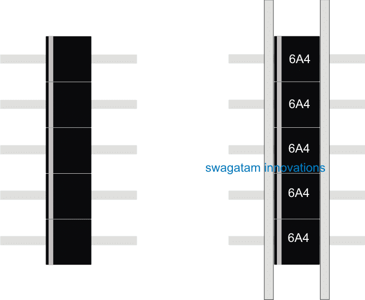
Referring to the figures we can witness a simple diode assembly clamped with heasinks. The diodes are 6A4 type diodes, I have selected these bigger diodes in order to acquire larger surface area and better conduction rate.
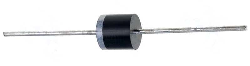
Diode 6A4
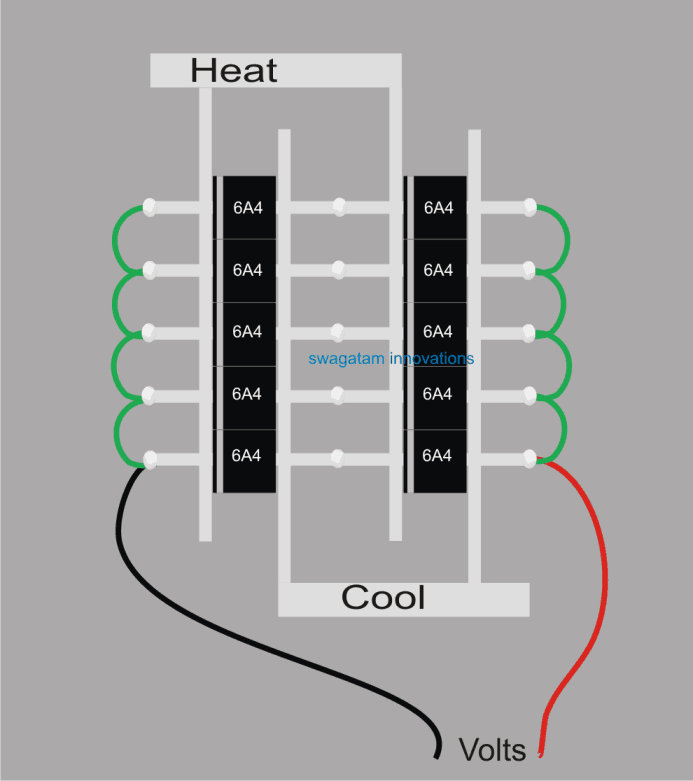
The simple thermoelectric generator circuit set up shown above could be possibly used for generating electricity from waste heat, by suitably applying the required degrees of heat difference across the indicated heat conducting plates.
The right side figure shows many diodes connected in series parallel connections for achieving higher efficiency and proportionately higher accumulation of potential difference at the output.
Why Use a Diode for Making a TEG
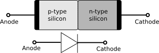
I have assumed that diodes would work for this application since diodes are the fundamental semiconductors units consisting of a doped p-n material embedded within their two terminating leads.
This also implies that the two ends are specifically composed of the diverse materials facilitating easier application of temperature separately from the two opposite ends.
Many such modules could be built and connected in series parallel combinations for achieving higher conversion rates, and this application could be implemented using solar heat also. The side which needs to be cooled could be achieved through air cooling or through an enhanced evaporative air cooling from atmosphere for increasing the efficiency rate.


Comments
how would one actually make a circuit from this? could you just connect stuff directly to the TEG or do you need he diode? What is its actual use?
Hi, The diodes are the elements which make the TEG system work…they are the ones which sense the temperature difference across their terminals and force electrons to flow…in this setup you can connect a voltmeter to check the voltage level and then if it god enough, then maybe you can try hooking up an LED and see if it illuminates or not…
what temperature difference is needed? how much electricity is produced? could I use heat pipes as a source? could the device be used to run a sterling engine. i picked up several stove fans for the peltier devices.
The voltage and current output will be very small…it is only for experimental purpose.
SO we take liquid nitrogen which is -300F for the cold side and will keep forever so long as it is sealed in a container.
The hot side is anyplace on earth, even the north poll isn’t -300f.
Next we just need to build the device to power you house or car…. forever.
So better step by step instructions as I just need to build the teg part please.
it won’t work
you need to heat or cool the PN junction
then heat both outlets when cooling the case
heat P cool N heat
or
cool P heat N cool
Im so interested of this new thermoelecric generator sir..thanks again and again
Hello sir, with your permission i would like to make this “TEG” , i have bought those 10, 64A diodes. Can you please help me to complete these connections with heat and cold sources. Please do mail me the procedure if possible, thanking you in advance.
Hello Charan, you can try it with a single diode. Connect a millivoltemeter across the diode, then heat the cathode side lead with soldering iron and check the response on the meter. If it shows some reading then you can add more combinations of diodes as shown in the diagram for getting more output from the set up
Sir, i want to make the exact model of the above fig which you have mentioned, please do let me know how to connect heat and cold sources, i am requesting you…please
Please try with a single diode as I suggested if you succeed in getting a positive response, then you can replicate the full model..the cold side can be water, and hot side from a soldering iron
you are welcome Mark!
Ah ok sir I got it..thank you alot sir swagatam..days I found your website I learned alot f your ideas.God bless you more sir swagatam
Hi Mark, the heat difference can be applied anyway round, the response will be either the generation of positive current or negative current depending on how the heat is polarized
Hi hello sir swagatam..this heat and cool you write above is atouched to the anode(cool) and cathode (heat) ?