In this post I have explained the making of an RTD temperature meter circuit, and also learn about different RTDs and their working principles through formulas.
What's an RTD
A RTD or resistance temperature detector works by detecting the difference or an increase in the resistance of the sensor metal when it's subjected to heat.
This change in the temperature of the element being directly proportional to the heat, provides a direct reading of the applied temperature levels.
In this article I have explained how rtds work and also how to make a simple high temperature sensor circuit using a homemade RTD device.
A direct reading in the form of varying resistance values can be obtained by heating an ordinary "heater coil" or an "iron" element.
The resistance being directly equivalent to the subjected heat, corresponds to the applied heat and becomes measurable over an ordinary digital Ohm meter. Learn more.
How RTD Temperature Meters Work
All metals have this fundamental property in common, that is they all change their resistance or the degree of conductance in response to heat or rising temperatures.
The resistance of a metal increases as its heated and vice versa. This property of metals is exploited in RTDs.
The above variation in the resistance of the metal is obviously related to electric current and means that if current is passed through a metal which is subjected to some temperature change will offer corresponding levels of resistance to the applied current.
The current also therefore varies proportionately with the varying resistance of the metal; this variation in the current output is directly read over an appropriately calibrated meter.
This is how basically a RTD temperature meter functions as a thermal sensor or transducer.
RTDs are commonly specified at 100 Ohms , which means that the element should show 100 Ohms resistance at zero degree Celsius.
RTDs are generally made up of the noble metal Platinum due to its excellent metallic characteristics like inertness to chemicals, good linear response to temperature versus resistance gradient, large resistance temperature coefficient, providing wider range of measurements, and stability (ability to hold temperatures and restrict sudden change).
Main Parts of an RTD
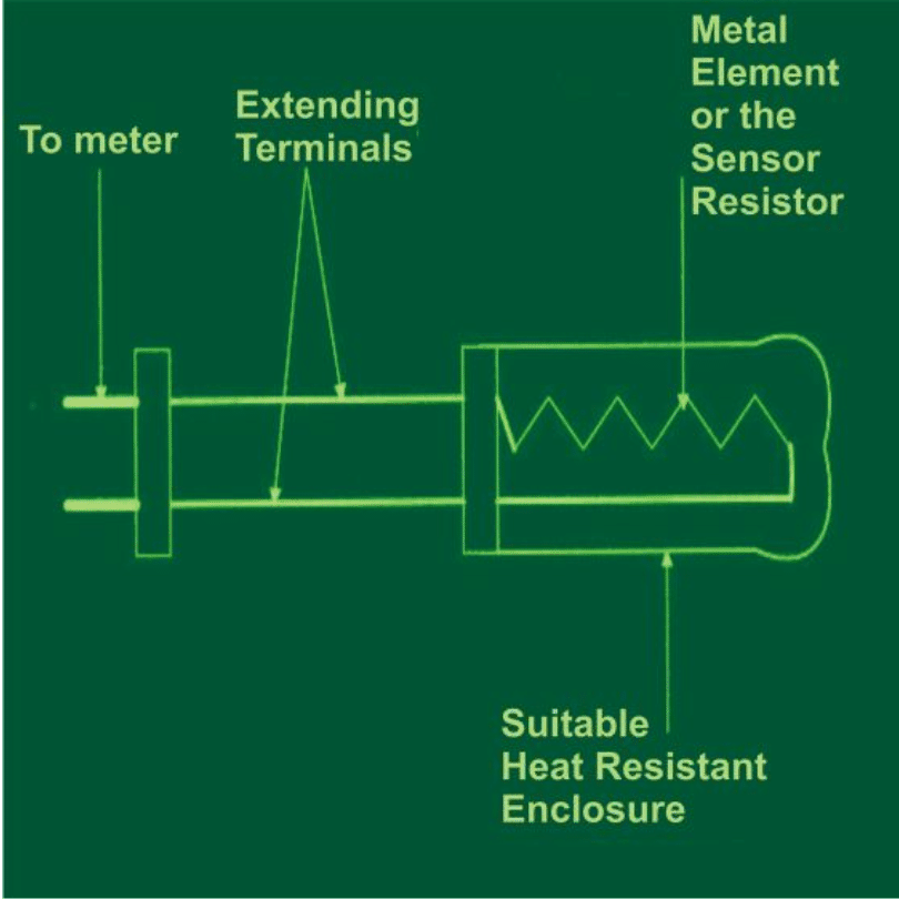
The above figure of a simple RTD temperature meter shows the basic design of a standard RTD device. It’s a simple type of thermal transducer comprising the following main components:
An outer enclosure, that’s made up of some heat resistant material such as glass or metal and sealed externally.
The above casing encloses a thin metal wire which is used as the heat detecting element.
The element is terminated through two external flexible wires which acts as the current source for the transducer or the enclosed metal element.
The wire element is precisely set inside the enclosure so that it’s proportionately spread across the whole length of the enclosure.
What is Resistivity
The basic working principle of RTDs is based on the fact that most conductors show a linear variation in their fundamental characteristic (conductance or resistance), when subjected to varying temperatures.
Precisely it’s the resistivity of the metal that changes significantly in response to varying temperatures.
This variation in the resistivity of a metal corresponding to the applied temperature changes is termed as resistance temperature coefficient or alpha and is expressed through the following formula:
alpha = d(rho)/dT = dR/dT ohms/oC (1)
where rho is the resistivity of the element or the wire metal used, R is its resistance in Ohms with a specified configuration.
How to Calculate Resistivity
The above formula can be further applied for determining the temperature of an unknown system through the general expression of R as given in the following equation:
R = R(0) + alpha (0 degree + Tx), where R(0) is the resistance of the sensor at zero degree Celsius and Tx is the temperature of the element.
The above expression can be simplified and written as:
Tx = {R – R(0)}/alphaTherefore, when R = R(0), Tx is = 0 degree Celsius, or when R > R(0), Tx > zero degree Celsius, however at R > R(0), Tx < 0 degree Celsius.
It will be important to note that, to achieve reliable results while using RTDs, the applied temperature must be uniformly distributed over the entire length of the sensing element, failing to do so may result inaccurate and inconsistent readings at the output.
Types of RTDs
The above explained conditions referred to the functioning of a two-wire type basic RTD, however due to many practical constraints a two-wire RTD are never accurate.
To make the devices more accurate additional circuitry in the form of a wheatstone bridge is normally incorporated.
These RTDs can be classified as the 3-wire and the 4-wire types.
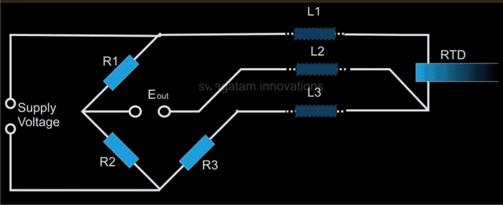
Three Wire RTD:
The diagram above shows a typical 3 –wire RTD connections. Here, the measuring current flows through L1 and L3 whilr L3 behaves just as one of the potential leads.
So long as the bridge is in the balanced condition, no current passes across L2, however L1 and L3 being in separate arms of the wheatstone network, the resistances get nullified and assumes a high impedance across Eo, also resistances between L2 and L3 are held at identical values.
The parameter ensures the use of a maximum of 100 meters of wire to be terminated from the sensor up to the receiving circuit and yet keep the accuracy within 5% of tolerance levels.
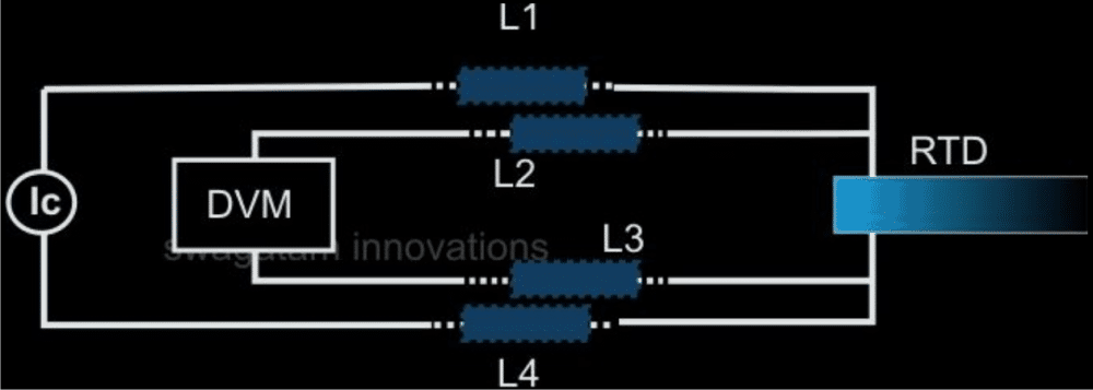
Four Wire RTD
The four wire RTD is probably the most efficient technique of producing accurate results even when the actual rtd is placed at far away distances from the monitor display.
The method cancels out all lead wire discrepancies to produces extremely accurate readings. The principle of operation is based on supplying a constant current through the RTD and measuring the voltage across it through a high impedance measuring device.
The method eliminates the inclusion of a bridge network and yet provides much credible outputs.
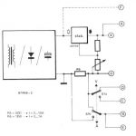
The figure above shows a typical four wire RTD wiring layout; here a precisely dimensioned constant current derived from a suitable source is applied through L1, L4 and the RTD.
A proportional result becomes directly available across the RTD through L2 and L3 and can be measured with a high impedance DVM, irrespective of its distance from the sensing element.
Here, L1, L2, L3, and L4 which are the resistances of the wires, become insignificant values that have no influence on the actual readings.
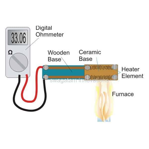
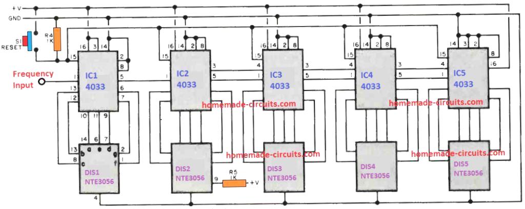
How to Make a Homemade RTD High Temperature Sensor
A high temperature sensor unit can be designed by using an ordinary "heater element" like a heater coil or an "iron" element. The principle of operation is based on the above discussions.
The connections are simple and needs just to be constructed as shown in the following DIAGRAM.

Comments
Circuit Diagram Please
You can try this:
https://www.homemade-circuits.com/100-c-to-1000-c-thermocouple-temperature-meter-circuit/