In this post I have explained about a car voltage stabilizer circuit which could be made and installed in all cars for ensuring a perfectly controlled and stabilized supply for the associated sensitive electronics and gadgets.
Understanding Car Electrical
A car electrical is probably more volatile than our house electrical, simply because it is generated from a source called alternator whose output considerably varies with the speed of the vehicle.
It means if you are driving your car with sudden changes in its speed or if you are often applying brakes, would consequently generate varying voltages from the alternator outputs.
Since nowadays our car and other vehicle interiors heavily involve sophisticated electronic gadgets, an unstable voltage conditions can cause serious effects on their performance and life.
The circuit idea was requested by Mr.Haziq, let's know more about the making of the proposed circuit (designed by me for the application).
Today we have some wonderful ICs at our disposal which are specifically designed for voltage regulation applications.
The LM317 and the LM338 are a couple of them which are versatile with their voltage regulation functions, I have discussed them elaborately in some my earlier posts.
The LM317 can handle up to 1.5 Amps while its big brother the LM338 can hold not more than 5 Amps.
However these values are quite meager when compared to the huge asks in automobiles.
By suitably modifying the configurations, the IC can be made to regulate any desired levels of currents though.
In the proposed car voltage stabilizer circuit we incorporate the IC LM317 and modify its standard design such that it enables the car electrical with sufficient power and yet restricts it from all possible dangers like overloads, over current, fluctuating voltages and short circuits, providing an ideal voltage conditions for the vehicle interiors.
Circuit Operation
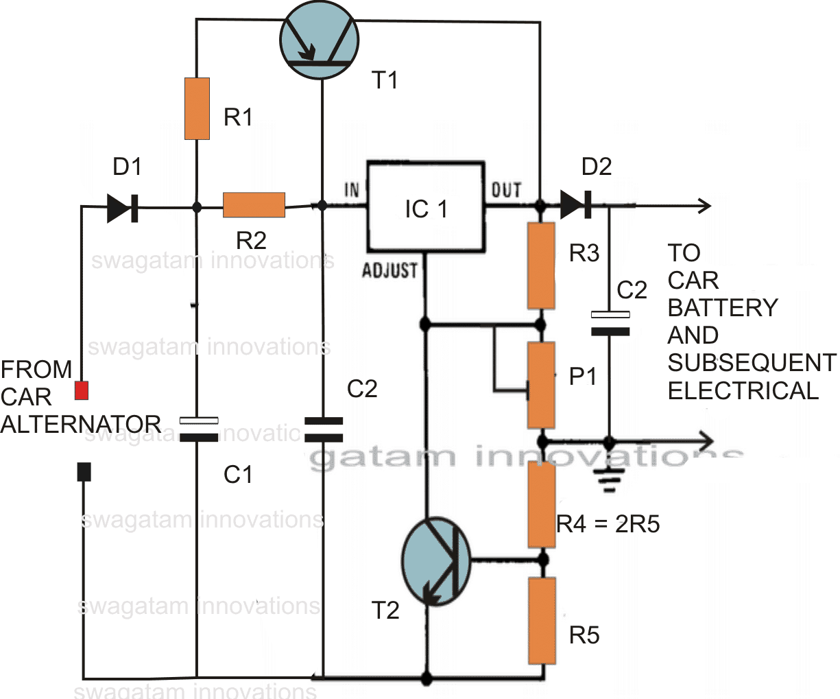
The circuit diagram shows a rather simple configuration where the IC 317 has been wired in its standard voltage regulator mode.
R1 limits the surge current, while R2 decides the triggering voltage to T1, if the current consumption crosses the 1.5 amp mark, T1 conducts and assists the IC by sharing the excess current through it.
P1 is set for achieving around 13 volts across C3.
R5 monitors over load conditions and short circuits, if the current crosses beyond 12 amps, sufficient current develops across R5 to trigger T2, which instantly switches OFF the IC so that the output voltage drops and restricts the current below 12 amps.
Ideal Specifications:
- Constant voltage = 13 volts
- Current Limit = 12 Amp
- Overload protection = above 12 amp cut OFF
- Thermal protection (if the transistor and IC are mounted on the same heatsink with mica isolation)
- Short circuit protection (fire hazard protection)
Parts List
- R1 = 0.1 Ohms, 100 watts, made from 1mm iron wire.
- R2 = 2 Ohms, 1 watt,
- R3 = 120 Ohms, 1/4watts,
- R4 = 0.1 Ohms, 20 watts, as explained for R1 (this resistor is actually not required, may be replaced with a wire short.)
- R5 = 0.05Ohms, 20 watts, make as R1
- T1 = MJ2955 mounted on big finned type heatsink
- T2 = BC547,
- C1 = 10,000uF, 35V
- C2 = 1uF/50V
- C3 = 100uF/25V
- P1 = 4k7 preset,
- IC1 = LM317
- D1, D2 = 20 amp diode (3nos. 6 amp diodes in parallel)
Simplified Version
Using the IC LM196, the above configuration becomes extremely simple, you may refer to the following diagram which illustrates a simplified version of the proposed car alternator voltage stabilizer circuit using bare minimum components.
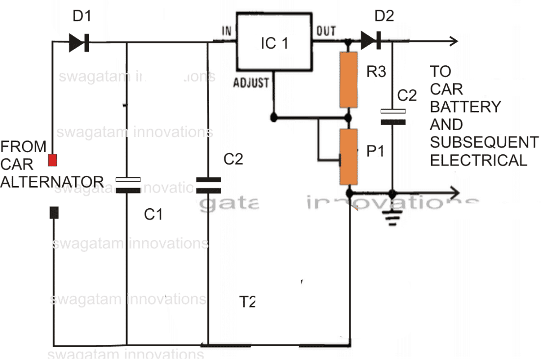
- R3 = 240 ohms
- D1, D2 = 15 amp diodes
- P1 = 10k preset
- C1,C2,C3 as specified above
- IC1 = LM196


Comments
you can try this circuit:
easy-electronic-circuits.blogspot.in/2013/09/uhf-fm-remote-control-transmitter.html
Hi Swagatam
All cars/trucks are equipped with a Voltage Regulator which supply regulated to the battery and the entire electrical system of the vehicle.
Earlier these voltage regulator were mechanical relay type, installed as an individual component. But nowadays, these v/regulators are mostly electronic type (much simpler based on three transistors) and are built within the alternator.
Furthermore, all the gadgets are duly protected with their respective fuse.
I wonder what extra benefit we can get with above-mentioned circuits.
Hi Abu-Hafss,
the above designs hopefully show a simpler approach to making these devices, anybody who may be interested to manufacture them or has a damaged system in his car can try this design.