In this article I have explained how to build a simple room ionizer circuit for getting a clean, pollution free environment right inside our home.
Introduction
Have you ever thought or wondered why atmosphere over hill stations and other similar places which are far away from modern cities give you a feeling of freshness and good health?
The answer is simple, the air in such places are free from pollutants and harmful chemicals like smoke and gases.
WARNING: THE CIRCUIT EXPLAINED IN THIS ARTICLE IS NOT ISOLATED FROM MAINS AC, AND IS THEREFORE EXTREMELY DANGEROUS TO TOUCH IN OPEN AND UNCOVERED CONDITION. NECESSARY PRECAUTIONS TO SAFEGUARD FROM AN ELECTRIC SHOCK IS STRICTLY RECOMMENDED. ALTHOUGH THE WORKING OF THE CIRCUIT IS TESTED, THE HEALTH BENEFITS OF THIS IONIZER CIRCUIT HAVE NOT BEEN VERIFIED BY THE AUTHOR. IF YOU ARE BUILDING THIS PROJECT, YOU AGREE THAT YOU ARE BUILDING IT AT YOUR OWN RISK.
A Must for City Like Delhi
Delhi, the capital of India is today severely struggling with air pollution crises. The issue has become so serious that it has been entitled as the highest priority among all the other ongoing health issues, and has reached an emergency level.
Although tough efforts are being implemented, still it seems the conditions isn't improving a bit, in fact the situation is getting even grimmer by the day.
A cheap solution like the proposed room air ionizer seems to be a very handy tool which can not only help control Delhi pollution, but also provide individual houses with reasonably pure air. This equipment can be used in houses, as well as in cars for the intended remedy.
Well, if you are settled in one of those cities which is engulfed with bad air and if you have compromised with the situations, here's your chance to get rid of the situation through the circuit I have explained below:
What is an Air Ionizer - How it Works
An air ionizer or as some may refer it as a room ionizer is basically a device or electronic circuit which is designed for generating voltage at the level of kilo-volts for implementing the said ionizing effects. So what's ionizing after all?
The high voltage that's generated from an ionizer is actually tuned for generating a negative voltage, at around minus 4 kV. This high negative voltage is allowed to get terminated over an open ended sharp conductor tip or point that's sharply carved.
When the voltage reaches at this sharp point, it tends to continue its forward motion and gets shot or released into the air in the form of negatively charged ions.
Once in the air these ions become free to move around and start getting dispersed across the room or the premise, as more and more ions are released from the air ionizer device.
Now as these ions roam freely in the air it comes across and starts colliding with the already present pollutants like dust particles, smoke/gas particles etc in the air.
As per the rules all particles and all materials present around should be positively charged, so what happens, the oppositely charged ions starts collecting these pollutants from the air by attracting them toward them (opposites attract), just as a magnet bar would do to iron pins.
The pollutants in the air slowly find themselves pulled and firmly stuck over these ions until each of the ions become so much pollutant laden and heavy that they start crashing on the ground or if they find a wall nearby they start gathering on it.
In this way the air in the course of time becomes absolutely clean and free from all impurities.
Circuit Operation
The circuit is quite simple and can be built even by a layman, having just basic knowledge of electronics.
The circuit is fundamentally based on Cockroft-Walton Ladder Network, The concept makes use of a network of many diodes and capacitors arranged in such a way that the applied voltage to it gradually becomes stepped up to very high levels, in the order of around 10kV,
However a 10kV range is not suitable for the discussed ionizing effects, in fact at this level the effect might produce opposite results.
If we go by calculations the present design would also generate around -10kV, spoiling the intended cause, however practically it is found to be dropping to about -4kV.
This reduction happens due to radiation losses, because in the course of its stepping up, the voltage tends to spark through emissions across the PCB until finally the resultant voltage at the output tip of the device reaches only up to around -4kV which is by God's grace the exact level for achieving the ionizing effect.
Circuit Diagram
The entire circuit may be built over a general purpose board, by soldering the shown number of capacitors and diodes exactly in the way they are arranged in the diagram.
Following the diagram pattern would make the making easier to assemble and would produce guaranteed results without faults.
After the circuit is assembled, check the entire board for any wring connections, this is important because the circuit is very critical with its polarities, a single wrongly connected diode would make the results zero.
After proper confirmation, the soldered side should be thoroughly cleaned with thinner so that no residual flux stays deposited causing loss of voltage and reduction in the desired effects.
The end which is terminated for releasing the ions must be needle shaped, preferably a small pin or needle can be used there for enabling perfect prorogation of the ions.
After all the above precautions are complete, it's time to power the unit. Be extremely careful, as the entire circuit is connected directly with mains AC and can be life threatening if touched in the powered position.
Verifying the Working of the Circuit
Once the circuit and if hopefully everything is rightly done with the assembly, you would hear a "hissing" noise near the tip of the releasing pin point. The area near the tip of the pin would give you a cooler sensation like a cool breeze flowing out.
The point would also produce a fish like smell.....all the above indications would confirm that the unit is working right and you are already breathing fresh air around your nose and heading toward a healthy life.
THE ABOVE CIRCUIT WAS SUCCESSFULLY BUILT AND TESTED BY ONE OF THE KEEN FOLLOWERS OF THIS BLOG, MR. ALI ADNAN.
THE FOLLOWING BEAUTIFUL PICTURES WERE SENT BY HIM.
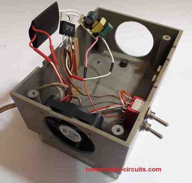
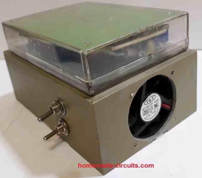
Prototype Pictures

The above room ionizer circuit was also successfully built and implemented by one of the dedicated readers of this blog "Ersa". The following tested working prototype images were sent by Ersa for our viewing pleasure.


Questions & Answers
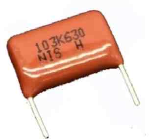
Hi. Great project, I want to make my ionizer. So, the value of the caps are 630V103J (if I read correctly) but the size ? are 1 cm ?
Hi, thanks, glad you liked the project, that’s right, the capacitors should be 0.01uF/630 V rated ideally, and must be PPC type.
Hi Sir.
Is this type of capacitor the right one?
630V103J 0.01UF Pitch 10MM 10NF 630V 103 CBB Polypropylene film capacitor.
Thanks
Hi Rosario,
it looks OK to me but physically these must be exactly similar to the ones which are shown in the prototype images.
Good day sir. I want to try the construction of the air ionizer circuit for home, but I have a question.
Is -4kV dangerous to human life or kills when the needle is mistakingly touched?
Hello Emmanuel,
According to the previous information I could gather -4kv is good for health. However I have not verified the results so cannot confirm the results. The needle will not produce an electric shock due to the presence of the high value series resistors.
Please read the warning message at the start of the article before trying this circuit.
Ok. Thanks so much.
Dear Sir Swagatam
Hello
Referring to your notice denoting “please keep up the good work”, I am going to send you pictures of your room air Ionizer circuit that I made one year ago. I hope that my experiences would be useful for your visitors.
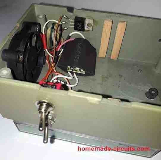
After a month passed from working the circuit, I noticed that everything around the unit including curtains, wall, etc., had been covered with a black layer and I found that the origins of it were, Charged ionized particles floating in the air. In order to solve the problem I inserted the needle of the ion spreading into a plastic box, I made two nos of 5 cm diameter holes on both sides of the box for the air to enter and exit; I accommodated a 12v dc fan on one side of the box and a piece of facial tissue inside the box to absorb the ionized particles and do not let them to spread in the air and make black and dirty everything around the air room ionizer unit. In order to reduce the sound of the fan, I reduced the speed of it which worked with the help of a 15v 300mA dvd driver, I added a 8v regulator IC to the unit
Everything is good now and I am very satisfied with it. I thank you so much for your very good circuit.
Wish you all the best
Ersa
Thank you so much Ersa,
I saw the pics and they look amazing.
Yes the black color deposit is due to the dust particles which get attracted by the negative ions and stick to the nearest neutral background which happens to be the walls or the carpets. I am glad you could modify the prototype and very intelligently solve the problem, and I am happy that everything is running smoothly now.
I will surely check out the diagrams and upload in the above article soon.
Again please keep up the good work 🙂
Dear Sir Swagatam
Hello. Thank you very much for encouraging me and I thank you so much for publishing the pictures and that you described scientifically the reason why dust particles, including carbon particles stick to environmental things.
I praise you for being so kind and generous, and wish you long-lasting joy and health.
Best regards
Ersa
Thank you so much Ersa,
Wish you all the best and God bless you!
how many volts is the high voltage?
I have a design with 30 diodes and 30 capacitors. Can I put more?
It is -4kv. If you put more diodes the output voltage may increase beyond -4kv and then it won’t serve the room ionizer purpose
I feel 1M Resistor should be in series with the Circuit. It is Shown across two input lines & may this Short the
Circuit. KINDLY CONFIRM
Actually there should be a series neon lamp with the 1M resistor which is mistakenly not shown in the diagram. However, even if you connect a 1M directly across the mains it will not create a short circuit because 1M is a very large value and will have no effect on the circuit.
Dear Sir Swagatam Thank you very much for sharing your knowledge
Kind regards
Ali
You are welcome Ali!
Hi Sir Swagatam. I want to assemble this circuit in a way that I can get more power (current) at the output. would you please tell me how much could be the utmost value of capacitors. I think 1N4007 diodes would be perfect for capacitors with more value.
Thank you in advance
Regards
Ali
Hi Ali, increasing capacitor value might result in the circuit producing ozone instead of negative ions, so it won’t be a good idea to increase capacitor value. Instead you can build many of these units and use them together for getting the desired amplified results.
Hi Sir Swagatam. I have recently read somewhere that ozone gas smells like fresh garlic. Isn’t it a good idea to build one on breadboard and smell it? may be the problem would be solved for ever Sir
Kind regards
Hi Ali, According to me ozone gas or any ionic gas produce smell of a rusted wet iron….so I am not sure about the garlic like smell
Hi, Thanks for providing the nice negative ion making circuit and explanation. Can I use it in cleaning of positively charged cat’s hair from my cloth or mat, will this device help me in that work.
Regards
Hi, thanks for liking the post! I don’t think the ions produced by the unit will be so powerful to lift and clean cat’s hair. It is designed to clean only microscopic particles, a cat’s hair looks to big to be attracted by this circuit.
Perfect, thank you for replying Swagatam!
I just have one more question… what do I use to connect the energy flowing from the adapter/transformer to the circuit/capacitor board?
Hope you’re having a nice day again 🙂
You are most welcome, the inverter output can be connected to the ionizer through a pair of ordinary flexible copper wires. Or simply the transformer output wires can itself be directly hooked up with the ionizer supply input
Good morning Swagatam,
I’m not sure if this discussion forum is still active, but I would GREATLY appreciate a response!
I find your instructions and insight for this project to be super useful as I have been searching for a way to build a working negative-ion generator for quite a while!
Even though I will be able to access both the diodes and the capacitors, I’m a little confused about the energy source. Would it be possible for me to use a battery for this experiment, or does the generator need to be plugged into a wall?
Finally, this is a science experiment for one of my classes, so do you suggest any tips or tricks to make this work more effectively since it’s been over a year since this article was published?
Thank you very much 🙂
Thank you Aubrey, and glad you liked the post.
The circuit must be built exactly as shown, using the exact components as indicated in the diagram, unfortunately there are no tricks to make it work more effectively, except increasing or deceasing the output voltage, which can be done by increasing or reducing the capacitor/diode stages accordingly.
I found the capacitor to be very crucial, and it must exactly the ones shown in the diagram. Once I tried making the project using ceramic 1kv type capacitors and it simply failed to work.
You can use a lead acid battery, but the battery power will need to be first converted to an AC, and then fed to the ionizer circuit.
One example concept can be found in the following article:
Make this Car Air Ionizer Circuit
Hi Swagatam
Thanks for the info on the LED indicator just saw the circuit, nice
All the best to you
Regards
Vee
Thank you Vee, hope it serves the intended purpose!
Hi Swagatam
I have an Air purifier for my bedroom and its plugged into a smart plug which is programmed to come ON at night and switch OFF in the morning.
As this unit runs very silent I am not sure whether its ON on not, so I want to add an LED as an indicator, so can you help me with a circuit for adding the same to the 120VAC supply to this unit
Thanks
Vee
Hi Vee,
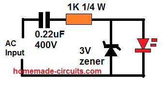
you can try the following circuit:
Please remember that the circuit is not isolated from the mains, therefore it can be extremely dangerous to touch it in the powered condition.
Can i connect more needle points… say 4 in total paralled with the one in cct but spaced apart. Also the neon indicator lamp is not shown in the cct diagram but is seen in the photograph i presume this lamp is connected across the mains input via a suitable current limiter resistor.
…..yes the neon is optional and is connected across the mains AC lines
More needle points will reduce the transmitting intensity of the needles, proportionately…
The mk3 is on the bench, using 30x 220nF caps. I’ll keep you posted.
I haven’t decided whether to use 1 or 2 carbon brushes yet.. The mk2 has 2 brushes and is fantastically powerful, but I wonder whether it would have been even better with only 1, as the mk1 had.
I made 2 like the mk1 (22nf x 24), adding a switch to the 2nd (before retrofitting switches to all 3) and higher resistance (40M) at the HV end, as the first (with 20M) was not reducing the current quite enough to be unnoticeable when touching the output!
I have 40M on the mk2 (100nF x 30) and even then it’s a bit tasty!
Also thanks Abu-Hafss for the sim. Very valuable!
I changed the Max input voltage to 340, as this is the peak to peak which gives RMS of 240V, as UK mains supply value.
I’ve added a switch to each now, as per your simulation circuit, after getting zapped by the plug pins one too many times! I used dpst on live and neutral as the caps will discharge (through you) via either pin..
Thankyou for this Swagatam!
I have built several of these in the last month or so, the first with 24x 22nF caps (12 stage) the 2nd with 30x 100nF – this mk2 version is extremely powerful. The voltage in the air near the emitters reaches over -120V, compared to around -3V max from my shop bought PureMate one! (the mk1 with 22nF, even, reads around -50V)
I used carbon fibre brushes for the emitters which gives a massive improvement over using needles. I just bought some non-woven carbon fibre tape and made the brushes using BigClive’s method.. I got this idea originally from a small car ioniser I have (AirTamer) which is very high output compared to my other commercially available (needle) ones. However, even the AirTamer’s output is nowhere near these DIY versions, at about -5V, simply measured in the air with a grounded multimeter.
I epoxied all of the solder joints, as any sharp edges will produce unwanted ionisation within the box, and reduce the desired output. I wonder if this is the reason these are so much more powerful than the commercial ones..? It is otherwise essentially the same circuit (mountain breeze, etc.)
You are welcome Jose,
Actually the output current from the device is extremely low, may be in microamps, so I doubt if this potential is measurable with a DMM. The current is too low to sustain through the probes of the meter.
Yes that’s right, the black air tight insulation sealing all around the PCB and the circuit drastically helps in improving the emission power of the unit
Hi, thanks for the quick reply. I too would have thought it unlikely to be able to measure the voltage in the air but it is indeed possible! I’ll send you a video clip if you like (email?)
I’ve seen other people’s videos where they attach an antannae of sorts (copper or other metallic sheet, croc clipped to the DMM lead) but I find this makes little difference to the reading – the potential can be measured directly with the probe.
Hi, yes it may be possible but the results won’t be correct on the meter. Because, the emitter is indeed emitting upto -4kv which is difficult to capture and check on the general purpose meters.
I agree entirely, it is not an accurate or meaningful measurement of output as such, but rather it is an indication of the relative power of this one compared to the ones I bought. The PureMate (PM-100) measured between -2v or -3V at about 1 cm away from the needles, but this reading would drop quite quickly. The mk1 version I made measures around -50v DC at same 1 cm distance – and this value drops much more slowly. The mk2 (100nf x 30) measures a sustained -120V at 1cm.
The PureMate one, however, has a gounded plate in front of the needles to increase the ‘ion wind’, with holes for the points to partially poke through, and the ozone generated thus is quite high! (This method is used in pure ozone generators, as it increases the strength of the corona discharge – but also reduces the negative ion output as a lot of the charge is dissipated through the grounded plate). I modified that PureMate one, disconnecting the grounded plate, rearranged the needle assembly infront of the plate which also mounted the needles via insulated bushings, and added carbon fibre tips instead. The output wasn’t increased all that much (still around -3V max.) but there was a massive reduction in the ozone smell…
All the best, Jose
OK, thanks for the interesting feedback!
Hello, I could not set up the circuit with proteus. If you have installed from another program before, can you throw it? 🙂
Hello, I built it practically with real parts, did not simulate.
Hello, I made this project with,
30x 22nF 630v
30x 1N4007
1x 4.7mOhm resistor before the needle
Powered by 220v ac.
However some of the caps burned in the first try. I dont know where did I make a mistake? Can anyone help me to fix that?
Hi, the capacitor cannot burn, they should be virtually indestructible with their 630 V rating, I think your caps may be faulty or duplicate quality…
is there any range?i mean can it purify a entire house?if it does how much time it would take on average consider a regular room size.
The results are actually time dependent and how well the room is sealed from all sides. For quicker results you may have to install at least one unit per wall
for a small room closed from all sides may take up to 5 hours to clean up
Hi, No, 275 V will not work, it should be over 600 V, and also it should metallized polyester type.
The LIVE/Neutral orientation does not matter, you can put the inputs any way round
Hi
Can you mix .01uF/600V capacitor with .02uF/600V capacitor?
Thanks
Hi, yes you can do that!
hello sir
I have a question
is there a sensor for this ions?I mean once we make these negative ions with this circuit,we could monitor them to know how many ions have been made.
thanks for the answer
can you guide me a bit more about how to make this air ion counter?
there are some parts in this pdf file that I don’t understand
it would be really good if you give me your email or whats app number so I can communicate with you
Pooya, Here’s a simple negative ion meter circuit that I got from an online source, you can build this to check the level of ions generated by the above circuit:
Hi pooya, you can use an air ion counter or an pollution meter or air quality meter to measure the working and effectiveness of the circuit
https://iopscience.iop.org/article/10.1088/1742-6596/1172/1/012010/pdf
Greetings,
Sir,
Appreciate for your great attempt.I assemble the unit and work satisfactorly on first attempt.And put this unit on newly painted room for sometime the smell of paint vanished..!!!.amazing..keep post such good ideas.Also we are expecting more health related article from you..ie..professional muscle stimulator with variant pulse modes.Any way thanks alot
That’s great Sisoncs, I am glad the circuit served the purpose! I’ll surely consider your suggestions and try to post it soon…keep up the good work!
Hi,
I made this circuit.
Initially there was some fishy smell surrounding the pin. But after sometime it stopped, before I could test it for hissing sound or visually seeing the glow on the tester or the smoke test.
I feel one of the condenser may have blown. Is there a way to check for the faulty condenser? Some of the condenser may be highly charged!!!
Hi, Sorry to hear that, however identifying the faulty capacitor quickly can be quite difficult because the capacitor might have not blown with any burn marks. It might have got damaged internally. The only way to check it is to break the connections of each capacitor and then check them individually using a capacitance meter.
If you have connected the 1M resistor then the capacitors might discharge through it within a few seconds, still to further confirm you can drag the plug pins of the connected cord over the leads of all the capacitors a couple of times.
Thank you for the guidance.
I was able to locate 3 defective capacitors and replaced it.
However following are the observation of the circuit before and after the replacement of the defective capacitors and also request your feed back on the query below:
—While trying to discharge the capacitors (in order to replace the defective), I noticed only the 1st three or four capacitors exhibited visible spark as well as sound when running the plug pins over the leads of the capacitor – BOTH BEFORE AND AFTER THE REPLACEMENT.
—Further after the replacement in order to satisfy myself if circuit works, I used the circuit of “Main Hum Detector” to test it. although the LED does not light up when the antenna of the circuit is kept at proximity of the discharge pin of the ionizer, but it lights up only when the antenna touches the discharge pin.
—Finally, what is the role of the 1M resistor, can I replace it with variable 1M resistor to increase or decrease the discharge rate by varying the resistance?
I am glad you could troubleshoot the fault.
A hum detector cannot be used for verifying the results of this circuit. For quickly verifying the results you can use a Neon phase tester and place the screw driver tip around 1 cm above the antenna. A good circuit will cause intermittent bright glow on the neon lamp of the tester.
Other ways are to keep your ear close to the antenna, a good circuit will emit a weak hissing sound, accompanied with a fishy kind of smell, confirming the emission of ions.
Since all the capacitors are in series, sparking a few of them will be enough to discharge all of them. You can replace the 1M with a 100K resistor for faster discharging, lower than this value is not recommended.
What is the needle that is used and what is the material of the needle that is used?
Any sharp conductor will do, a normal sewing needle will also work…
A short length of coax (Arial cable) with the resistor connected to the outer braiding! Simply trim the insulation back at the other end to expose the copper braiding and straighten the ends out and you have got yourself an ion Arial! I did this by stripping the insulation fro the middle of a 6″ piece pf cable and bending it to exit out of 2 holes to double the number of exit points for the ions …. it worked well 😉
Thanks for the Update, appreciate it.
Hi I tried making this but not working pls help..
how can I help?
sir, how did you connect the sharp needle to the 2m2? just by electrical tape? thank you sir. (I am following the circuit diagram here: http://www.brighthubengineering.com/diy-electronics-devices/78220-simple-room-air-ionizer-and-purifier/#imgn_0)
I connected by soldering it.
Hi Swagatam,
I made this circuit today. I soldered the end to a needle. While testing with an Ion tester there is a pulsating glow indicating discharge of ion but, neither there is a hissing sound nor fish like smell, I could detect. It seems that the ion output is weak. Is it because I have used USHA PP 0.01 mfd 630v capacitors ?
That's great, I am glad you could succeed with the project.
all the reputed online electronic spare part stores are good, you can specify them the component type and make, and get the exact one delivered to you.
Thank you very much. It's indeed working. I could feel the cool breeze near the needle tip. Noe I will make another for my car and now I plan to use Philips capacitors. Can you suggest me a source for genuine electronic spares ? Thanks once again.
Hi Partha, if you are getting a fluctuating light in your line tester without touching it with the needle then definitely your circuit is working.
The hissing sound and the fish like smell can be too feeble and easily get diffused due to atmospheric disturbances, you must test these parameter inside a quite room with no breeze flowing, preferably switch OFF the fan while verifying them.
the noddle end is harmful by touching
no it is not
We already placed everything as the diagram shows. I alreay sent inages of our circuit. It was not working no cool breeze nor hissig noise. I don't know what mistake I made. I attached pictures to your email. Thanks!
either your connections has a fault or one of the parts or all the parts are not appropriately rated for this project.
the diodes should have thick leads and good print on it, that will indicate an original 1N34007 diode…thin leads with faint print can be duplicates.
capacitors should be preferably Philips made….others might or work might not work.
check out this article which shows my working prototype in it and the explanation.
http://www.brighthubengineering.com/diy-electronics-devices/78220-simple-room-air-ionizer-and-purifier/
Greetings. Is it okay to use 0.01uF/630V PP capacitor? Does it affects the output?
Hi, 0.01uF/630V is fine, no it won't affect the output…
Sir, may I ask 'you can connect the body or the plates to ground or earth pin of your 3-pin socket' what will the best size an what type of plates to be used in a room of say 10×10 ft. Thanks.
Thanks very much for the reply.
A 4×4 feet will be enough…and it does not need to be metal or connected to earth…..
sir, does the 10uf capacitor have to be of polyester material? i bought one of the same value (10 uf 630 volts, color red but its not polyester)
it's not 10uF, it 10nF…please make sure you read the instructions and the parts carefully before trying…
sir, what did you use to power the circuit since i can only see two wires connecting to it? thank you so much
Maxine, the two wires go to the mains 220V or 120V source…
I made the circuit based on your design. It does not produce any ion effect.
I used a Line tester to see if the current is flowing, and the tester lights up on touching every diode connection as well as on the pin after the three 3M3 resistors.
I have used Two-watt 3M3 resistors.
How can i share the pics with you?
I have replied to your email.
what will happen if i choose 22uf capacitor? will the circuit not work?
the current at the output will increase, but I am not sure about the consequences…
Question, Swagatam…. have you measured the anion output of your device?
No i did not measure the output, the only technical data I have is regarding the output voltage, which is around -4kv
What will happened if i using capacitors with higher capacity for example 1uF rather than 0.01uF? Is that help to increase the efficiency?
probably the current will increase resulting in stronger ion generations….
sorry that may not be possible, because boosting a 9V low current to 4kv may ultimately be so weak that it won't initiate any ionization.
Thank you for your replay!
I'm sorry for my english 🙁
however, why did you put 3 resistors after the last diode?
the 3 resistors in series is to ensure 100% safety at the needle point against the minutest of electric shocks for the users.
Hi Sir,
first of all congratulations for your web-site!!
I have 2 questions for you:
1-I'd like connecting a box with inside an electrified grid for purifying air: where do I connect the electrified grid to build an ionizing filter? after the 3 3M3 resistors?
2-How long this circuit can stand on?Are there some risks for extended use?
Thank you very much for your help.
Gabri
Thanks Gabri,
sorry i could not understand your first question??
2) the circuit can last forever, just make sure to paint the whole PCB with a thick layer of oil paint after confirming its working….this is to safeguard the circuit from moisture, corrosion etc.
thank you
hi sir.thank you for this nice circuit. i have a question. can i use more needles to make more ions in this circuit?
Hi, No that's not possible, in fact increasing the number of needles will dilute the force of the ions and make the emission weaker..
Sir, Ita really usful one but how to check it is working?
I have explained it in the article and the comments…please go through it comprehensively.
If i use less caps (to increase voltage), and use more needles (how about 3),
than, i can gain my scheme till 12 kV and in result (12 kV / 3 needles = 4 kV per needle).
Is it correct? or i didnt understand the shematic till end?
sorry that's not possible…Google "Cockroft-Walton Ladder Network" for learning more about the concept
Good day sir, i just want to ask if there will be a problem if i dont follow the way the components are connected. I want to try this for my project but i need to apply a pcb design for it. Thanks !
5 needles will divide the voltage into 5….that would do no good to the results…it's better to use a single needle
I have another question sir. is it okay if i used 5 needles for this project ?
yes it'll if many are employed…
i have another question sir. is this ionizer also neutralize the odor in the air ? thanks again sir.
Menardo, it's recommended to align and connect the parts precisely in accordance with the diagram, otherwise there could be a possibility of a mistake and confusions
Dear Sir,
Should this circuit also work with 0.1uF capacitor? (same type and voltage as yours)
Thanks!
Thank you for your response!
Dear Andre, 0.1uF will produce higher current which may not be recommended for an ionizer because that can alter the specified health benefit results in an adverse way…
but it will work.
Dear Sir,
Thank you very much for your co-operation. I have a small doubt. The voltage at the final connection will be 6kV, which will generate negative ions. But we are reducing the voltage to some 40v with 2.2M resistance. will the pin, which is having a voltage of 40v will generate ions? else, can we connect the pins directly without using resistance?
Regards,
CH M S SARMA
What exactly do you want a build? If you are interested to make a room ionizer then you should make the design that's shown above without any changes, if you are planning to build a high voltage generator in that case you can try the idea that you have mentioned.
Dear Sir,
Can we increase the capacitor power and reduce the number of Capacitors? because I want to build a compact one.
Thanks
CH M S SARMA
Dear Sarma,
who says it's reduced to 40V?? the tip of the 2m2 resistors will be also around -4kV (not 6kv)…but at extremely low current….resistance is required to prevent high current and electric shock at the emitter
Dear sir,
I have connected the emitter pin. But if the AC power is reversed 40V current is coming to the pin. I cannot hear any sound from the pin. Can you suggest me anion tester circuit with LED? I have checked all the capacitors before connecting. One more thing…. I have checked the voltage from capacitor to capacitor. At the. Second one it is 60v 2nd to 3 Rd 30v and at 5 th it is showing 0v. That means the voltage is going to negative? What ever it is, finally I could not confirm that the circuit is working. Can I get a build circuit from you?
Regards
Ch M S SARMA
Dear Sarma,
AC power does not have a polarity, no matter how you connect it to the circuit, there will no difference in the result…the circuit will continue to generate the negative ions.
I made this unit when I was just 17 years old, and I did not have any trouble in making it work immediately.
I built this the second time recently around 5 years ago, again I could make it work successfully but only at the second attempt, because in the first attempt I used low quality capacitors and it failed to produce any results, then I changed the capacitors with good ones and could instantly see the unit work.
You can witness the prototype images in this website article:
http://www.brighthubengineering.com/diy-electronics-devices/78220-simple-room-air-ionizer-and-purifier/
here I have also shown the image of the prototype which failed to work due to bad capacitors (blue in color)
I might have the working model still lying somewhere in my junk box, but due to lack of time it won't be possible for me to upload a video here…
Dear sir,
I have sent you the pictures of the circuit. I have checked the voltage at each capacitors. Almost at all the capacitors the voltage is around 230v (from mains to each capacitors). Seems some mistake somewhere. Kindly advice.
Thanks
…I have seen the picture that you sent recently, and it's constructed as I suggested above, but I cannot see the emitter pin??
connect a sharp, very sharp emitter pin via a a few 2m2 resistors and take your ear close to it in a silent environment….you should be able to hear a low hissing sound…please check it
Dear Sarma,
measuring the voltages is not required and it won't help, there's no easy way to troubleshoot it expect checking the polarities and the quality of the components.
you'll have to assemble it again without using a PCB, as Mr. Adnan has done in the shown prototype.
Dear sir,
I have tested at the tip of the pin and current is coming. But there is no sound or light at the tip. I have used 30 nos 10nf 630V polyester capacitors and 1N4007 diodes. I checked all the diodes for continuity and confirmed that there is no continuity in the diodes. I have sent you the picture also. Is there any other way to check whether the ionizer is working or not?
Dear Sarma,
if there's no mild hissing sound, or fishy smell or light on a line-tester close to the tip of the emitter then it means your circuit is not working.
I saw the image sent by you, the capacitor specification looks OK but I could not see how you might have connected all the 30 diodes and the caps.
please repeat the assembly using new components and this time do it exactly as per the layout of the shown diagram, meaning you must connect all the capacitors and the diodes exactly in the manner indicated in the diagram….or you can simply make it by twisting and soldering the parts just as Mr.Adnan has done in his prototype.
Dear Sir,
Thank you very much for your immediate reply. I want to send you the pictures of my circuit. kindly let me know how to send the pictures. or you can give me your mail address. my mail id is sarma.challa@gmail.com.
Dear Sarma, you can send it to:
admin (at) http://www.homemade-circuits.com
Dear Sir,
I have made this circuit using .01 uF polyester Caps and IN4007 diodes. But I could not feel any sound or cooling effect at the needle tip. I have checked all the connections again and again. I have used 3mm SS Pins 10 Nos. at the end. I made the circuit with 30 caps. could you tell me where I might have gone wrong? The neon at the beginning is glowing. Is there any other way that we can check the emission of Ions? Kindly reply.
Dear Sarma,
the possible reasons could be either a wrongly selected capacitor specification or a wrongly connected diode….a faulty diode can also prevent the circuit from functioning normally.
most probably the capacitor could be of a wrong type…
an alternative way of checking is by keeping a line-tester around 1cm close to the tip of the emitter
Dearest Swagatam.
I'm estimating that for USA 110V mains, you would need 70 Diodes and Capacitors to reliably attain 4kV. Our Mains voltage varies slightly, here, from 108 to 125, but 70 should do ok for even 108.
Thanks,
–Tom
yes for 110V supply , you may need to double the number of diodes and the capacitors.
Oh.. I see, it is only using the negative half….. Gotcha, My mistake…. how could we invert the positive have of the AC wave to make use of it, I wonder?
Dearest Tom, the above circuit has been purposely designed in the shown manner (negative polarity) so that it generates negative ions which is considered to be beneficial in many ways…if we change the polarity of the diodes it will start producing positive ions which might be of no use, in fact harmful for the environment.
Dearest Swagatam.
Could one build the mirror image of this circuit in anti-parallel in order to take advantage of both halves of the AC waveform? Right now it is only using the Positive half, and blocking the negative half…
Thanks,
–Tom
Sí, es un multiplicador de tensión, la resistencia a la entrada es sólo para la descarga de todos los condensadores cuando el circuito está enchufado de la toma, esto es para evitar una descarga eléctrica al usuario de la descarga.
los 3m3 resistencias ar todo cuarto wa nominal y MFR tipo 1%
"hello, is it a voltage multiplier, but that resistance should not be used at the beginning of the circuit and if that is the principle bulb led and how much. Also at the end there are some resistance 3M3 … how much are they?"
Yes it is a voltage multiplier, the resistor at the input is just for discharging all the capacitors whenever the circuit is plugged out of the socket, this is to prevent an electric shock to the user from the discharge.
the 3m3 resistors ar all 1/4 wa rated and MFR 1% type
hola, es que yo ya hice el multiplicador de voltaje, pero no se que resistencia debo usar al inicio del circuito y si ese bombillo del principio es un led y de cuanto. tambien al final que hay 3M3 son resistencias cierto…de cuanto son?
breadboarding won't be a good idea, the best way of doing it is probably by twisting the leads and connecting, as done in the prototype sample because this method will prevent any chance of cross component leakages.
for me the design worked immediately after assembling, although I had assembled it on a PCB,
check the diode quality also, a duplicate brand can affect the results seriously.
….the recommended capacitor type will not show any leaking sign, a wrong diode connection or a poor quality diode or a duplicate diode can also cause problems in the circuit
thanks, removing the resistors will not impact the output emissions by much, the resistors are introduced to ensure maximum safety for the user from the mains.
Greetings. I also had success with building it in one try. I used copper to connect resistor to the needle. I have one question, can I remove one or two resistors from the end to get better result at my needle ?
hello Swagatam Majumdar, whether this circuit can be made by the board or PCB, let me look good
hello robert, yes it can be made over a dot matrix PCB
Did anyone (or can anyone) try what happens if you switch positive and negative voltage? That way, the device creates positive ions instead of negative ions. I'm very curious whether this way, it still removes dust/particles. In other words: Are most dust/particles in the air really positively charged?
thanks for the informations Amilcar, it's much appreciated!
Negative ions (anions) not only precipitate dust particles but also induce "good moods" in all living beings… plants, animals and humans alike. Natural sources of anions are waterfalls, fountains, rivers –in fact, any continuously running stream of water… like a shower.
Cations (positive ions), however, induce the opposite effects. I did an experiment a couple of years ago –just inverted the diodes like Swagatam said– and it induced headaches, anxiety and even breathing difficulties in everyone present. Not pleasant at all.
the polarity of the diodes will need to be changed for acquiring positive ions….this will not clean the dust particles as effectively as with negative ions…
Hi Swagatam,
i have made this circuit. I could not smell any thing near it, could not see sparks on pin top in the dark , and no sound. but when i place my tester near to pin a small sparks shows in the dark. Is my circuit ok? Is there any ions produced from pin??
Thank You
…the hissing sound will be heard when you bring your ear about 1cm close to the needle point, a tester is not needed for this.
Hi Rakibul, then most probably your circuit is working, it doesn't need to be built straight, can be in any form..as long as its built correctly.
hang your circuit somewhere on the wall switched ON for a couple of days, if the wall behind the circuit becomes blackish would confirm that the circuit is indeed responding well.
Hi Swagatam,
Thanks for reply, tester is glowing near 2 or 3 mm distance.i have another question? you made your circuit straight 'I', but my circuit is 'u' shaped. That is 220v is near to the 4kv point.Is there any problem with that? And I will hear sound when when neddle sparks to tester ? Right.
Thanks
Hi Rakibul, is the tester glowing when the tester is around 1cm near the needle without direct contact? If yes then your circuit may be alright and in this situation you should also get the fishy smell very close to the needle……. and under perfect silence you would also hear a hissing sound close to the needle.
Hi Swagatam,
Is it possible to incorporate a flow of ionised "air" in this circuit(Like a small fan or something)? I work with some plastic products, so flushing it a small stream of ionised air would be useful.
Thank you.
Hi Jithin,
I am sure if ions could be pushed with breeze, however since ions too have mass they could be influenced with air flow, ……you can try it.
May I ask a question? 1M resister is essential or not?
(Because I did not check 1M, it is not availiable right now.)
Actually there should be a neon bulb in series with the 1M, by mistake it's not shown in the diagram.
You can remove it anyway, if you wish!
Hi everybody
Want to see the simulation for this project?
Copy the long long link below, and paste in browser's address bar.
A java applet window will be opened, maximize it.
Close the switch at the top left and see the voltage going in -kV in the graph at the bottom.
Enjoy !!!
www.falstad.com/circuit/#%24+1+5.0E-6+10.20027730826997+50+5.0+50%0Ar+176+48+176+224+0+1000000.0%0Ar+224+48+224+224+0+1000000.0%0Ac+224+48+272+48+0+1.0E-8+9.999987702542512E-4%0Ad+272+48+224+224+1+0.805904783%0Ad+288+224+272+48+1+0.805904783%0Ad+336+48+288+224+1+0.805904783%0Ad+368+224+336+48+1+0.805904783%0Ad+400+48+368+224+1+0.805904783%0Ad+432+224+400+48+1+0.805904783%0Ad+464+48+432+224+1+0.805904783%0Ad+496+224+464+48+1+0.805904783%0Ad+528+48+496+224+1+0.805904783%0Ad+560+224+528+48+1+0.805904783%0Ad+592+48+560+224+1+0.805904783%0Ad+624+224+592+48+1+0.805904783%0Ad+656+48+624+224+1+0.805904783%0Ad+688+224+656+48+1+0.805904783%0Ad+720+48+688+224+1+0.805904783%0Ac+224+224+288+224+0+1.0E-8+9.999989198092862E-4%0Ac+288+224+368+224+0+1.0E-8+9.999990116966728E-4%0Ac+368+224+432+224+0+1.0E-8+9.999991506219885E-4%0Ac+432+224+496+224+0+1.0E-8+9.999993073961377E-4%0Ac+496+224+560+224+0+1.0E-8+9.999993337146407E-4%0Ac+560+224+624+224+0+1.0E-8+9.999994182123828E-4%0Ac+624+224+688+224+0+1.0E-8+9.999995329792455E-4%0Ac+272+48+336+48+0+1.0E-8+9.99998885021114E-4%0Ac+336+48+400+48+0+1.0E-8+9.999989554501099E-4%0Ac+400+48+464+48+0+1.0E-8+9.999990132598668E-4%0Ac+464+48+528+48+0+1.0E-8+9.999991021345522E-4%0Ac+528+48+592+48+0+1.0E-8+9.999992198004293E-4%0Ac+592+48+656+48+0+1.0E-8+9.99999331440904E-4%0Ac+656+48+720+48+0+1.0E-8+9.99999449192046E-4%0Aw+688+224+688+288+0%0Ac+688+288+624+288+0+1.0E-8+9.99999464454504E-4%0Ac+624+288+560+288+0+1.0E-8+9.999995556881913E-4%0Ac+560+288+496+288+0+1.0E-8+9.999996321710114E-4%0Ac+496+288+432+288+0+1.0E-8+9.999997343470568E-4%0Ac+432+288+368+288+0+1.0E-8+9.999998254670572E-4%0Ac+368+288+304+288+0+1.0E-8+9.999998571288415E-4%0Ac+304+288+240+288+0+1.0E-8+9.999999532226411E-4%0Ac+656+432+592+432+0+1.0E-8+9.999994042289018E-4%0Ac+592+432+528+432+0+1.0E-8+9.999994771590082E-4%0Ac+528+432+480+432+0+1.0E-8+9.999996160843239E-4%0Ac+480+432+400+432+0+1.0E-8+9.999997990064458E-4%0Ac+400+432+336+432+0+1.0E-8+9.999998376599706E-4%0Ac+336+432+272+432+0+1.0E-8+9.999999281546934E-4%0Ac+272+432+208+432+0+1.0E-8+0.0010000000340539827%0Ad+624+288+656+432+1+0.805904783%0Ad+592+432+624+288+1+0.805904783%0Ad+560+288+592+432+1+0.805904783%0Ad+496+288+528+432+1+0.805904783%0Ad+432+288+480+432+1+0.805904783%0Ad+368+288+400+432+1+0.805904783%0Ad+304+288+336+432+1+0.805904783%0Ad+240+288+272+432+1+0.805904783%0Ad+208+432+240+288+1+0.805904783%0Ad+272+432+304+288+1+0.805904783%0Ad+336+432+368+288+1+0.805904783%0Ad+400+432+432+288+1+0.805904783%0Ad+480+432+496+288+1+0.805904783%0Ad+528+432+560+288+1+0.805904783%0Ad+192+288+208+432+1+0.805904783%0Aw+720+48+720+432+0%0Aw+720+432+656+432+0%0Ac+240+288+192+288+0+1.0E-8+0.0010000000291654487%0Ar+160+560+320+560+0+3300000.0%0Ar+320+560+544+560+0+3300000.0%0Ar+544+560+784+560+0+3300000.0%0Aw+784+560+784+352+0%0Aw+192+288+160+288+0%0Aw+160+288+160+560+0%0Aw+224+224+176+224+0%0Aw+176+224+128+224+0%0Aw+224+48+176+48+0%0As+128+48+176+48+0+1+false%0Av+128+112+128+160+0+1+50.0+220.0+0.0+0.0+0.5%0Aw+128+160+128+224+0%0Aw+128+112+128+48+0%0Ao+68+64+0+35+2560.0+9.765625E-5+0+-1%0A
Thanks Abu-Hafss!