In this article I have explained how to build a simple room ionizer circuit for getting a clean, pollution free environment right inside our home.
Introduction
Have you ever thought or wondered why atmosphere over hill stations and other similar places which are far away from modern cities give you a feeling of freshness and good health?
The answer is simple, the air in such places are free from pollutants and harmful chemicals like smoke and gases.
WARNING: THE CIRCUIT EXPLAINED IN THIS ARTICLE IS NOT ISOLATED FROM MAINS AC, AND IS THEREFORE EXTREMELY DANGEROUS TO TOUCH IN OPEN AND UNCOVERED CONDITION. NECESSARY PRECAUTIONS TO SAFEGUARD FROM AN ELECTRIC SHOCK IS STRICTLY RECOMMENDED. ALTHOUGH THE WORKING OF THE CIRCUIT IS TESTED, THE HEALTH BENEFITS OF THIS IONIZER CIRCUIT HAVE NOT BEEN VERIFIED BY THE AUTHOR. IF YOU ARE BUILDING THIS PROJECT, YOU AGREE THAT YOU ARE BUILDING IT AT YOUR OWN RISK.
A Must for City Like Delhi
Delhi, the capital of India is today severely struggling with air pollution crises. The issue has become so serious that it has been entitled as the highest priority among all the other ongoing health issues, and has reached an emergency level.
Although tough efforts are being implemented, still it seems the conditions isn't improving a bit, in fact the situation is getting even grimmer by the day.
A cheap solution like the proposed room air ionizer seems to be a very handy tool which can not only help control Delhi pollution, but also provide individual houses with reasonably pure air. This equipment can be used in houses, as well as in cars for the intended remedy.
Well, if you are settled in one of those cities which is engulfed with bad air and if you have compromised with the situations, here's your chance to get rid of the situation through the circuit I have explained below:
What is an Air Ionizer - How it Works
An air ionizer or as some may refer it as a room ionizer is basically a device or electronic circuit which is designed for generating voltage at the level of kilo-volts for implementing the said ionizing effects. So what's ionizing after all?
The high voltage that's generated from an ionizer is actually tuned for generating a negative voltage, at around minus 4 kV. This high negative voltage is allowed to get terminated over an open ended sharp conductor tip or point that's sharply carved.
When the voltage reaches at this sharp point, it tends to continue its forward motion and gets shot or released into the air in the form of negatively charged ions.
Once in the air these ions become free to move around and start getting dispersed across the room or the premise, as more and more ions are released from the air ionizer device.
Now as these ions roam freely in the air it comes across and starts colliding with the already present pollutants like dust particles, smoke/gas particles etc in the air.
As per the rules all particles and all materials present around should be positively charged, so what happens, the oppositely charged ions starts collecting these pollutants from the air by attracting them toward them (opposites attract), just as a magnet bar would do to iron pins.
The pollutants in the air slowly find themselves pulled and firmly stuck over these ions until each of the ions become so much pollutant laden and heavy that they start crashing on the ground or if they find a wall nearby they start gathering on it.
In this way the air in the course of time becomes absolutely clean and free from all impurities.
Circuit Operation
The circuit is quite simple and can be built even by a layman, having just basic knowledge of electronics.
The circuit is fundamentally based on Cockroft-Walton Ladder Network, The concept makes use of a network of many diodes and capacitors arranged in such a way that the applied voltage to it gradually becomes stepped up to very high levels, in the order of around 10kV,
However a 10kV range is not suitable for the discussed ionizing effects, in fact at this level the effect might produce opposite results.
If we go by calculations the present design would also generate around -10kV, spoiling the intended cause, however practically it is found to be dropping to about -4kV.
This reduction happens due to radiation losses, because in the course of its stepping up, the voltage tends to spark through emissions across the PCB until finally the resultant voltage at the output tip of the device reaches only up to around -4kV which is by God's grace the exact level for achieving the ionizing effect.
Circuit Diagram
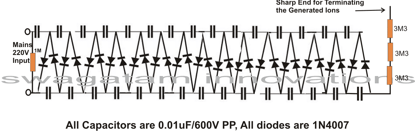
The entire circuit may be built over a general purpose board, by soldering the shown number of capacitors and diodes exactly in the way they are arranged in the diagram.
Following the diagram pattern would make the making easier to assemble and would produce guaranteed results without faults.
After the circuit is assembled, check the entire board for any wring connections, this is important because the circuit is very critical with its polarities, a single wrongly connected diode would make the results zero.
After proper confirmation, the soldered side should be thoroughly cleaned with thinner so that no residual flux stays deposited causing loss of voltage and reduction in the desired effects.
The end which is terminated for releasing the ions must be needle shaped, preferably a small pin or needle can be used there for enabling perfect prorogation of the ions.
After all the above precautions are complete, it's time to power the unit. Be extremely careful, as the entire circuit is connected directly with mains AC and can be life threatening if touched in the powered position.
Verifying the Working of the Circuit
Once the circuit and if hopefully everything is rightly done with the assembly, you would hear a "hissing" noise near the tip of the releasing pin point. The area near the tip of the pin would give you a cooler sensation like a cool breeze flowing out.
The point would also produce a fish like smell.....all the above indications would confirm that the unit is working right and you are already breathing fresh air around your nose and heading toward a healthy life.
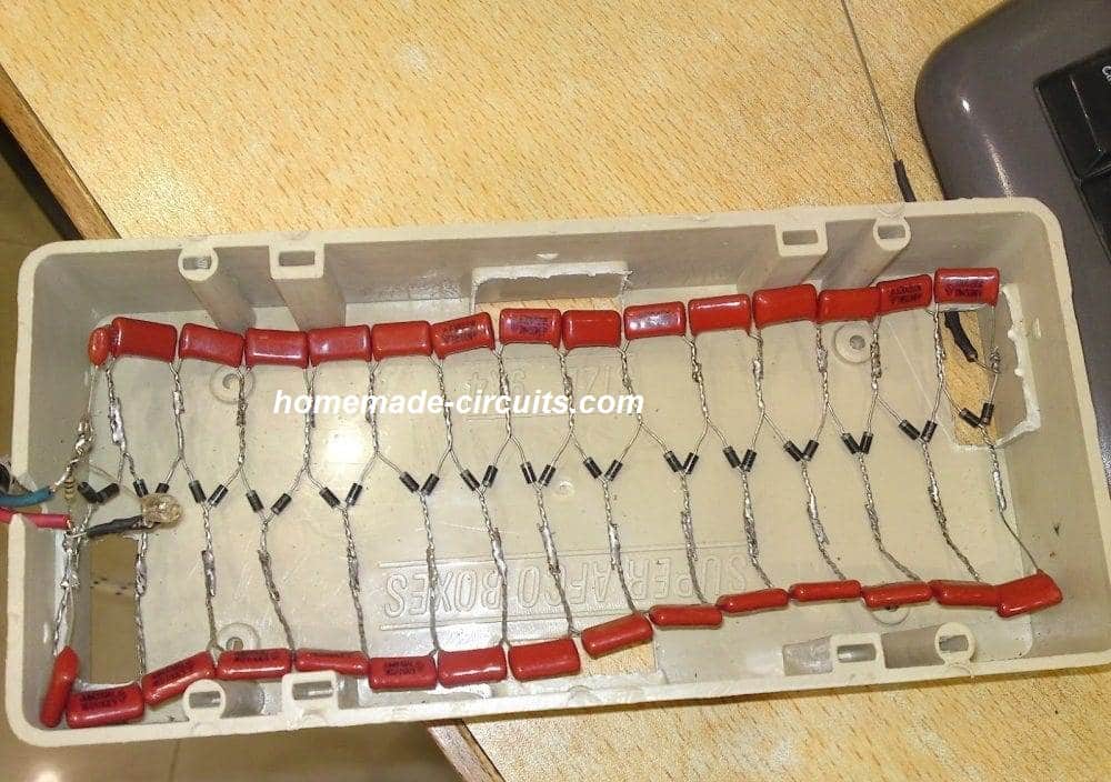
THE ABOVE CIRCUIT WAS SUCCESSFULLY BUILT AND TESTED BY ONE OF THE KEEN FOLLOWERS OF THIS BLOG, MR. ALI ADNAN.
THE FOLLOWING BEAUTIFUL PICTURES WERE SENT BY HIM.
Prototype Pictures

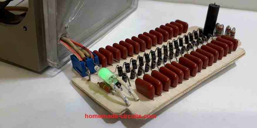
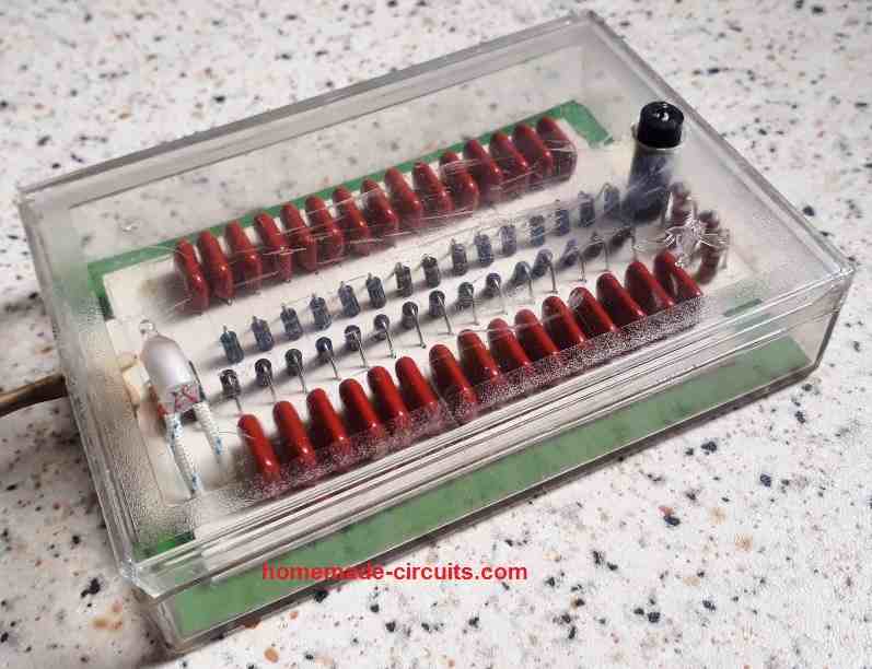
The above room ionizer circuit was also successfully built and implemented by one of the dedicated readers of this blog "Ersa". The following tested working prototype images were sent by Ersa for our viewing pleasure.



Questions & Answers
Hi everybody
Want to see the simulation for this project?
Copy the long long link below, and paste in browser's address bar.
A java applet window will be opened, maximize it.
Close the switch at the top left and see the voltage going in -kV in the graph at the bottom.
Enjoy !!!
www.falstad.com/circuit/#%24+1+5.0E-6+10.20027730826997+50+5.0+50%0Ar+176+48+176+224+0+1000000.0%0Ar+224+48+224+224+0+1000000.0%0Ac+224+48+272+48+0+1.0E-8+9.999987702542512E-4%0Ad+272+48+224+224+1+0.805904783%0Ad+288+224+272+48+1+0.805904783%0Ad+336+48+288+224+1+0.805904783%0Ad+368+224+336+48+1+0.805904783%0Ad+400+48+368+224+1+0.805904783%0Ad+432+224+400+48+1+0.805904783%0Ad+464+48+432+224+1+0.805904783%0Ad+496+224+464+48+1+0.805904783%0Ad+528+48+496+224+1+0.805904783%0Ad+560+224+528+48+1+0.805904783%0Ad+592+48+560+224+1+0.805904783%0Ad+624+224+592+48+1+0.805904783%0Ad+656+48+624+224+1+0.805904783%0Ad+688+224+656+48+1+0.805904783%0Ad+720+48+688+224+1+0.805904783%0Ac+224+224+288+224+0+1.0E-8+9.999989198092862E-4%0Ac+288+224+368+224+0+1.0E-8+9.999990116966728E-4%0Ac+368+224+432+224+0+1.0E-8+9.999991506219885E-4%0Ac+432+224+496+224+0+1.0E-8+9.999993073961377E-4%0Ac+496+224+560+224+0+1.0E-8+9.999993337146407E-4%0Ac+560+224+624+224+0+1.0E-8+9.999994182123828E-4%0Ac+624+224+688+224+0+1.0E-8+9.999995329792455E-4%0Ac+272+48+336+48+0+1.0E-8+9.99998885021114E-4%0Ac+336+48+400+48+0+1.0E-8+9.999989554501099E-4%0Ac+400+48+464+48+0+1.0E-8+9.999990132598668E-4%0Ac+464+48+528+48+0+1.0E-8+9.999991021345522E-4%0Ac+528+48+592+48+0+1.0E-8+9.999992198004293E-4%0Ac+592+48+656+48+0+1.0E-8+9.99999331440904E-4%0Ac+656+48+720+48+0+1.0E-8+9.99999449192046E-4%0Aw+688+224+688+288+0%0Ac+688+288+624+288+0+1.0E-8+9.99999464454504E-4%0Ac+624+288+560+288+0+1.0E-8+9.999995556881913E-4%0Ac+560+288+496+288+0+1.0E-8+9.999996321710114E-4%0Ac+496+288+432+288+0+1.0E-8+9.999997343470568E-4%0Ac+432+288+368+288+0+1.0E-8+9.999998254670572E-4%0Ac+368+288+304+288+0+1.0E-8+9.999998571288415E-4%0Ac+304+288+240+288+0+1.0E-8+9.999999532226411E-4%0Ac+656+432+592+432+0+1.0E-8+9.999994042289018E-4%0Ac+592+432+528+432+0+1.0E-8+9.999994771590082E-4%0Ac+528+432+480+432+0+1.0E-8+9.999996160843239E-4%0Ac+480+432+400+432+0+1.0E-8+9.999997990064458E-4%0Ac+400+432+336+432+0+1.0E-8+9.999998376599706E-4%0Ac+336+432+272+432+0+1.0E-8+9.999999281546934E-4%0Ac+272+432+208+432+0+1.0E-8+0.0010000000340539827%0Ad+624+288+656+432+1+0.805904783%0Ad+592+432+624+288+1+0.805904783%0Ad+560+288+592+432+1+0.805904783%0Ad+496+288+528+432+1+0.805904783%0Ad+432+288+480+432+1+0.805904783%0Ad+368+288+400+432+1+0.805904783%0Ad+304+288+336+432+1+0.805904783%0Ad+240+288+272+432+1+0.805904783%0Ad+208+432+240+288+1+0.805904783%0Ad+272+432+304+288+1+0.805904783%0Ad+336+432+368+288+1+0.805904783%0Ad+400+432+432+288+1+0.805904783%0Ad+480+432+496+288+1+0.805904783%0Ad+528+432+560+288+1+0.805904783%0Ad+192+288+208+432+1+0.805904783%0Aw+720+48+720+432+0%0Aw+720+432+656+432+0%0Ac+240+288+192+288+0+1.0E-8+0.0010000000291654487%0Ar+160+560+320+560+0+3300000.0%0Ar+320+560+544+560+0+3300000.0%0Ar+544+560+784+560+0+3300000.0%0Aw+784+560+784+352+0%0Aw+192+288+160+288+0%0Aw+160+288+160+560+0%0Aw+224+224+176+224+0%0Aw+176+224+128+224+0%0Aw+224+48+176+48+0%0As+128+48+176+48+0+1+false%0Av+128+112+128+160+0+1+50.0+220.0+0.0+0.0+0.5%0Aw+128+160+128+224+0%0Aw+128+112+128+48+0%0Ao+68+64+0+35+2560.0+9.765625E-5+0+-1%0A
Thanks Abu-Hafss!
May I ask a question? 1M resister is essential or not?
(Because I did not check 1M, it is not availiable right now.)
Actually there should be a neon bulb in series with the 1M, by mistake it's not shown in the diagram.
You can remove it anyway, if you wish!
Hi Swagatam,
Is it possible to incorporate a flow of ionised "air" in this circuit(Like a small fan or something)? I work with some plastic products, so flushing it a small stream of ionised air would be useful.
Thank you.
Hi Jithin,
I am sure if ions could be pushed with breeze, however since ions too have mass they could be influenced with air flow, ……you can try it.
Hi Swagatam,
i have made this circuit. I could not smell any thing near it, could not see sparks on pin top in the dark , and no sound. but when i place my tester near to pin a small sparks shows in the dark. Is my circuit ok? Is there any ions produced from pin??
Thank You
Hi Rakibul, is the tester glowing when the tester is around 1cm near the needle without direct contact? If yes then your circuit may be alright and in this situation you should also get the fishy smell very close to the needle……. and under perfect silence you would also hear a hissing sound close to the needle.
Hi Swagatam,
Thanks for reply, tester is glowing near 2 or 3 mm distance.i have another question? you made your circuit straight 'I', but my circuit is 'u' shaped. That is 220v is near to the 4kv point.Is there any problem with that? And I will hear sound when when neddle sparks to tester ? Right.
Thanks
Hi Rakibul, then most probably your circuit is working, it doesn't need to be built straight, can be in any form..as long as its built correctly.
hang your circuit somewhere on the wall switched ON for a couple of days, if the wall behind the circuit becomes blackish would confirm that the circuit is indeed responding well.
…the hissing sound will be heard when you bring your ear about 1cm close to the needle point, a tester is not needed for this.
Did anyone (or can anyone) try what happens if you switch positive and negative voltage? That way, the device creates positive ions instead of negative ions. I'm very curious whether this way, it still removes dust/particles. In other words: Are most dust/particles in the air really positively charged?
the polarity of the diodes will need to be changed for acquiring positive ions….this will not clean the dust particles as effectively as with negative ions…
hello Swagatam Majumdar, whether this circuit can be made by the board or PCB, let me look good
hello robert, yes it can be made over a dot matrix PCB
Greetings. I also had success with building it in one try. I used copper to connect resistor to the needle. I have one question, can I remove one or two resistors from the end to get better result at my needle ?
thanks, removing the resistors will not impact the output emissions by much, the resistors are introduced to ensure maximum safety for the user from the mains.
….the recommended capacitor type will not show any leaking sign, a wrong diode connection or a poor quality diode or a duplicate diode can also cause problems in the circuit
breadboarding won't be a good idea, the best way of doing it is probably by twisting the leads and connecting, as done in the prototype sample because this method will prevent any chance of cross component leakages.
for me the design worked immediately after assembling, although I had assembled it on a PCB,
check the diode quality also, a duplicate brand can affect the results seriously.
hola, es que yo ya hice el multiplicador de voltaje, pero no se que resistencia debo usar al inicio del circuito y si ese bombillo del principio es un led y de cuanto. tambien al final que hay 3M3 son resistencias cierto…de cuanto son?
Sí, es un multiplicador de tensión, la resistencia a la entrada es sólo para la descarga de todos los condensadores cuando el circuito está enchufado de la toma, esto es para evitar una descarga eléctrica al usuario de la descarga.
los 3m3 resistencias ar todo cuarto wa nominal y MFR tipo 1%
"hello, is it a voltage multiplier, but that resistance should not be used at the beginning of the circuit and if that is the principle bulb led and how much. Also at the end there are some resistance 3M3 … how much are they?"
Yes it is a voltage multiplier, the resistor at the input is just for discharging all the capacitors whenever the circuit is plugged out of the socket, this is to prevent an electric shock to the user from the discharge.
the 3m3 resistors ar all 1/4 wa rated and MFR 1% type
Dearest Swagatam.
Could one build the mirror image of this circuit in anti-parallel in order to take advantage of both halves of the AC waveform? Right now it is only using the Positive half, and blocking the negative half…
Thanks,
–Tom
Oh.. I see, it is only using the negative half….. Gotcha, My mistake…. how could we invert the positive have of the AC wave to make use of it, I wonder?
Dearest Tom, the above circuit has been purposely designed in the shown manner (negative polarity) so that it generates negative ions which is considered to be beneficial in many ways…if we change the polarity of the diodes it will start producing positive ions which might be of no use, in fact harmful for the environment.
Dearest Swagatam.
I'm estimating that for USA 110V mains, you would need 70 Diodes and Capacitors to reliably attain 4kV. Our Mains voltage varies slightly, here, from 108 to 125, but 70 should do ok for even 108.
Thanks,
–Tom
yes for 110V supply , you may need to double the number of diodes and the capacitors.
Dear Sir,
I have made this circuit using .01 uF polyester Caps and IN4007 diodes. But I could not feel any sound or cooling effect at the needle tip. I have checked all the connections again and again. I have used 3mm SS Pins 10 Nos. at the end. I made the circuit with 30 caps. could you tell me where I might have gone wrong? The neon at the beginning is glowing. Is there any other way that we can check the emission of Ions? Kindly reply.
Dear Sarma,
the possible reasons could be either a wrongly selected capacitor specification or a wrongly connected diode….a faulty diode can also prevent the circuit from functioning normally.
most probably the capacitor could be of a wrong type…
an alternative way of checking is by keeping a line-tester around 1cm close to the tip of the emitter
Dear Sir,
Thank you very much for your immediate reply. I want to send you the pictures of my circuit. kindly let me know how to send the pictures. or you can give me your mail address. my mail id is sarma.challa@gmail.com.
Dear Sarma, you can send it to:
admin (at) http://www.homemade-circuits.com
Dear sir,
I have tested at the tip of the pin and current is coming. But there is no sound or light at the tip. I have used 30 nos 10nf 630V polyester capacitors and 1N4007 diodes. I checked all the diodes for continuity and confirmed that there is no continuity in the diodes. I have sent you the picture also. Is there any other way to check whether the ionizer is working or not?
Dear Sarma,
if there's no mild hissing sound, or fishy smell or light on a line-tester close to the tip of the emitter then it means your circuit is not working.
I saw the image sent by you, the capacitor specification looks OK but I could not see how you might have connected all the 30 diodes and the caps.
please repeat the assembly using new components and this time do it exactly as per the layout of the shown diagram, meaning you must connect all the capacitors and the diodes exactly in the manner indicated in the diagram….or you can simply make it by twisting and soldering the parts just as Mr.Adnan has done in his prototype.
Dear sir,
I have sent you the pictures of the circuit. I have checked the voltage at each capacitors. Almost at all the capacitors the voltage is around 230v (from mains to each capacitors). Seems some mistake somewhere. Kindly advice.
Thanks
Dear Sarma,
measuring the voltages is not required and it won't help, there's no easy way to troubleshoot it expect checking the polarities and the quality of the components.
you'll have to assemble it again without using a PCB, as Mr. Adnan has done in the shown prototype.
…I have seen the picture that you sent recently, and it's constructed as I suggested above, but I cannot see the emitter pin??
connect a sharp, very sharp emitter pin via a a few 2m2 resistors and take your ear close to it in a silent environment….you should be able to hear a low hissing sound…please check it
Dear sir,
I have connected the emitter pin. But if the AC power is reversed 40V current is coming to the pin. I cannot hear any sound from the pin. Can you suggest me anion tester circuit with LED? I have checked all the capacitors before connecting. One more thing…. I have checked the voltage from capacitor to capacitor. At the. Second one it is 60v 2nd to 3 Rd 30v and at 5 th it is showing 0v. That means the voltage is going to negative? What ever it is, finally I could not confirm that the circuit is working. Can I get a build circuit from you?
Regards
Ch M S SARMA
Dear Sarma,
AC power does not have a polarity, no matter how you connect it to the circuit, there will no difference in the result…the circuit will continue to generate the negative ions.
I made this unit when I was just 17 years old, and I did not have any trouble in making it work immediately.
I built this the second time recently around 5 years ago, again I could make it work successfully but only at the second attempt, because in the first attempt I used low quality capacitors and it failed to produce any results, then I changed the capacitors with good ones and could instantly see the unit work.
You can witness the prototype images in this website article:
http://www.brighthubengineering.com/diy-electronics-devices/78220-simple-room-air-ionizer-and-purifier/
here I have also shown the image of the prototype which failed to work due to bad capacitors (blue in color)
I might have the working model still lying somewhere in my junk box, but due to lack of time it won't be possible for me to upload a video here…
Dear Sir,
Thank you very much for your co-operation. I have a small doubt. The voltage at the final connection will be 6kV, which will generate negative ions. But we are reducing the voltage to some 40v with 2.2M resistance. will the pin, which is having a voltage of 40v will generate ions? else, can we connect the pins directly without using resistance?
Regards,
CH M S SARMA
Dear Sarma,
who says it's reduced to 40V?? the tip of the 2m2 resistors will be also around -4kV (not 6kv)…but at extremely low current….resistance is required to prevent high current and electric shock at the emitter
Dear Sir,
Can we increase the capacitor power and reduce the number of Capacitors? because I want to build a compact one.
Thanks
CH M S SARMA
What exactly do you want a build? If you are interested to make a room ionizer then you should make the design that's shown above without any changes, if you are planning to build a high voltage generator in that case you can try the idea that you have mentioned.
Dear Sir,
Should this circuit also work with 0.1uF capacitor? (same type and voltage as yours)
Thanks!
Dear Andre, 0.1uF will produce higher current which may not be recommended for an ionizer because that can alter the specified health benefit results in an adverse way…
but it will work.
Thank you for your response!
Good day sir, i just want to ask if there will be a problem if i dont follow the way the components are connected. I want to try this for my project but i need to apply a pcb design for it. Thanks !
Menardo, it's recommended to align and connect the parts precisely in accordance with the diagram, otherwise there could be a possibility of a mistake and confusions
i have another question sir. is this ionizer also neutralize the odor in the air ? thanks again sir.
yes it'll if many are employed…
I have another question sir. is it okay if i used 5 needles for this project ?
5 needles will divide the voltage into 5….that would do no good to the results…it's better to use a single needle