In this article I have explained how to make a cheap yet effective mains operated AC overload and over-current protector circuit using very ordinary discrete components.
Introduction
I have published a few mains voltage stabilizer circuits in this blog, these units are designed and intended for safeguarding the connected appliances at their outputs.
However these equipment lack one protection which is the overload protection.
The Importance of an Overload Protection Circuit
A particular stabilizer unit may be rated for handling a maximum specified limit of power, beyond which it's effects may start diluting or might become inefficient.
Overloading a voltage stabilizer might also result in heating of the transformer and fire hazards.
A simple circuit shown below may be incorporated with a stabilizer circuit or any such protection circuit for reinforcing the safeguarding capabilities of the units.
How it Works
The diagram shows a very simple and straightforward configuration where only a couple of transistors and few other passive parts are used for forming the intending design.
The mains stabilized AC is derived from the stabilizer outputs and allowed to switch through another RL1, via its N/C contacts.
One of the wires of the AC mains connections is added with a series resistor of a calculated value.
As the load across the mains output increases, a proportionate magnitude of voltage starts developing across this resistor.
The value of the resistor is so selected that the voltage across it becomes just enough to light up a connected LED in response to a load that might be considered as dangerous and over the maximum tolerable limit.
When this happens, the LED just lights up, an LDR positioned and enclosed in front of the LED instantly drops its resistance in response to the illumination generated by the LDR.
The sudden reduction in the resistance of the LDR, switches ON T1 which in turn switches ON T2 and the relay, initiating the latching effect of the circuit and the relay.
The load or the appliance at the output is thus immediately switched off when an overload situation is detected.
The whole action takes place within a fraction of a second, giving no chance for any untoward consequence and the whole system is safeguarded by the inclusion of this simple AC mains overload protection circuit.
Formula for Calculating Current limiting Resistor
R1 = 1.5 / I(intended current limit),
For example if I =15 amps, then R1 = 1.5/15 = 0.1 Ohms, and it's wattage will be 1.5 x 15 = 22.5 watts
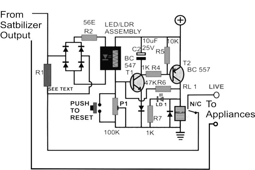
Parts List
- All resistors are 1/4 watt 5% except R1 (see text)
- R4 = 56 ohms
- R4, R7 = 1K
- R5 = 10K
- R6 = 47K
- P1 = 100K preset
- Diodes = All are 1N4007
- T1 = BC547
- T2 = BC557
- C2 = 10uF/25V
- LD1 = red LED 20 mA
- Relay = 12 V/200mA 30 amps
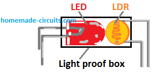
The LED/LDR device can be assembled manually as per the following example image



Questions & Answers
Hello Swagatam,
I want to apply this CKT to my Air Condition stabilizer which is 3Kva can you help me decide on the relay rating and R1 my AC is 1400Watts.
Regards,
Ajay
Hello Ajay,
Here are the details
3000/220 = 13 amps
Therefore R1 = 2v/13 = 0.15ohms 3watts
Relay contacts must be rated at 20 amps
…for 1400 watts it would be
1400/220 = 6.36amps
R1 = 0.3 ohms/ 2 watts
Relay contacts @10 to 12 amps.
How you are calculating power of resistor R1? P=I2XR or P=VI ? Please explain.
P = VI….V = voltage drop across resistor
Hello sir Swagatam. I really appreciate your effort. I’ve been looking for an overload protection for inverter circuit. You have so far referred me to two post but this one is just the perfect one for the intended purpose. I’ve read through the comments and have gotten more info from your responses. Thank you sir. I have a few questions:
1. In your response above as regards how to calculate the sensing resistor wattage, you said that: P = VI, V = voltage drop across resistor. How do we determine this voltage?
2. I want to design the circuit in such a way as to use it to power off the inverter when overload is sensed at the transfo output. So i want to use a smaller relay such that the contacts will be used to disconnect power to the inverter oscillator during overload condition. So what i want to do is to allow the output of the transfo to pass through the sensing resistor directly to the load. Can i go ahead with that arrangement?
3. From the schematic, which side/pin of C2 is positive?
Hello Godson, you can use the relay contact for the mentioned purpose, so in that case connect the indicated relay contact wire directly with the load.
watt of the resistor will be = bridge drop + LED drop / shut down current
= 1.2 + 1.5 / D current.
the white side of c2 is the positive.
Please pardon me sir, I still don’t fully understand the explanation you gave in your response to how to calculate the wattage of the sensing resistor. Please could use the example you gave above for a 3KVA inverter to explain, I’ll understand it better that way. Thank you sir.
Godson, the wattage will equal to the voltage drop across the resistor multiplied by the shut down current limit selected by you.
the voltage drop across the resistor can be achieved by adding the bridge rectifier drop (approximately 1.2V) and the LED FWD voltage drop (approximately 2V)
Hello Swagatam,
Thanks for the quick response, to be very precise I have recently bought a Hitachi AC model RAW318KTD, my previous AC compressor was blown due to the stabilizer was generating 300VAC. I have got the stabilizer repaired how ever want to be very cautious this time.
My AC specs are Current drawn-4.7 amps, Rated power supply -(230/50/1 Volts/Hz/Phase), Total Power input-1055 Watts.
Sorry for bothering you again.
Regards,
Ajay
Hello Ajay,
You will need an over voltage protector circuit in that case. You can make the following circuit:
https://www.homemade-circuits.com/2011/12/simple-mains-ac-over-voltage-and-under.html
It will protect your AC from high voltages as well as low voltages.
Hello Swagatam,
Thanks very much for your kind and prompt response, need your advice to decide on the relay and T1, as I will be using a relay that can bear a minimum load of 15Amps, and have decide to build the the following:
https://www.homemade-circuits.com/2011/12/simple-mains-high-and-low-voltage.html
Regards,
Ajay
Hello Ajay
You may use the relay which is shown below:
OEN/12V/285ohms/16amp/SPDT
please, what is the function of P1?
For adjusting the sensitivity of the circuit….
Thank you for the answer on P1 but what is the value of R2. Is it 56 ohms?
yes 56 ohms, it's the LED current limiting resistor
Thank you very much. I will build this circuit using an optocoupler and give you feedback.
Hi Swagatam,
Just like your voltage stabilizer circuit using opamps, I have also tried this circuit (with an optocoupler) and it works. But it triggers quite often even when there is not so much load. Adjusting the preset does not help. Any ideas?
Hi Vijay,
did you calculate R1 correctly? please calculate such that the opto led lights up only when there is a true overload as per the required specifications.
alternatively you may also try adding a 1uF capacitor across base and ground of the T1
Yes, I used two .47E resistors in series as I couldn't get 1 ohm for a 3amp load. Anyway, I'll try again and update.
Thanks,
Vijay
OK! thanks
Hi Swagatam,
I redesigned this circuit and assembled. As my stabilizer is 1KVA and it can handle 4A, I have used a 1ohm 20W resistor as the voltage sensor. I know this is a little high value but I have created a voltage divider using a 10K preset and adjusted the voltage so that only at 4A the optocoupler is triggered. Even that's not perfect because even a tiny current through the optocoupler triggers T1. To mitigate this I played around and connected a 100K resistor between the optocoupler and T1 base. I tried the 4A current using an induction stove, set the power at 1000W, and I measured exactly 4A using a multimeter. This seems to work fine. When I increase the power to 1200W, it triggers.I haven't yet tried 1050W, 1100W etc yet, which I'll do a little later. While doing this, I found another issue; when I connect the output to my voltage stabilizer (already assembled using one of your circuits but this is 500VA), because of the inrush current to the autotransformer, the circuit triggers. I mitigated this issue by connecting a 47mf capacitor (anything less doesn't do the trick) between P1. Now when I increase the power to 1200, the circuit triggers but takes about 1 second to do so.
I have one query: Since this circuit allows a second of over current, will it damage the autotransformer? I feel it can take more current than it is rated at for some time but I just wanted to be sure.
Thanks,
Vijay
Hi Vijay, congrats to you!
You have done all the modifications correctly, and everything seems perfect to me, a 1 second delay will not affect your autotransformer in any manner, because before getting damaged the transformer will first have to heat up, and when it reaches above 150 degrees only then it might start smoking and this might take more than 20 to 30 seconds.
By the way what did you use for the opto coupler? is it a readymade LED/phototransistor opto or the recommended LED/LDR type homemade opto?….the LED/LDR would provide better and more reliable results compared to the conventional one.
Hi Swagatam, Thanks. I used MCT2E. I was thinking of trying an LED/LDR combo if 100K between MCT2E and T1 base didn't do the trick but it did.
Vijay
OK, that's fine Vijay, everything's well that ends well..
Hello Sir
Just stumbled upon this post.
Since vijay made it work then I think I can use it as an overload protector with some changes
1) I get rid of the relay and instead pass the positive signal from collector of PNP transistor to pin10 of my sg3524.
2) while I am studying the other post you referred me to this one looks more sophisticated.
3) where and how will I include a time delay before passing to in 10 of IC so the when the current goes above the limit it first gives a de lay of say 5secs and if load does not reducez current then it shuts off inverter
4) if per adventure the load settles to normal like in the case of surge loads capacitor should discharge rapidly so that it does not trigger shut down since starting current has reduced to normal
Hello Michael,
for including a delay effect, you can simply add a high value capacitor across the base and ground of T1…make sure the signal from the opto comes through a resistor if you are using an opto coupler…this resistor value can also be tweaked for setting the delay response
Hello sir
I don't quite get how vijay set up the 1ohm 20w and the 10k preset.
Then what value can we use for P1.
Also there seem to be some confusion as to how to calculate R1 value as I read through the comments.
Hello Michael, the delay effect shouldn't be so critical actually….and yes all the above parameters will interact some and influence the delay effect, so it may require a little experimentation until the right delay is determined…
Sir assuming i want to use this circuit for 3kv inverter overload protection how could i calculate R1? sir the relay connection it seem not clear well to me, first, connection to coil terminal is not show in the circuit,secondly, N/O terminal and N/C seem some how confusion. Thanks, hope to hear from you soon.
Adelusi,
the formula is given in the article, please use it to calculate. the current limit in the formula could be calculated by dividing 3kv with the voltage.
please click the diagram to enlarge, you will be able to see both the contacts although slightly faded, but anyway the N/O is unconnected so its not important, the N/C is the one which is associated with the load and the current.
sir please kindly help me design a 12vdc to 36vdc converter.sir i am ready for any output services rendered.
you can try any IC 555 based boost converter circuit or 555 IC based flyback converter circuit, please Google this you will find many
Hiee sir
Can u tell about any circuit that will convert DC to ac (square wave).
Without using transformer.
Hi Nikhil, you can use the circuit which is shown in this article:
https://www.homemade-circuits.com/2014/01/simplest-full-bridge-inverter-circuit.html
Please there is a small confusion about the actual constant need for calculating various values of R1.. The post said 1.5 you said it is 2 and later said 3 so please explain the changes. Thanks
Here's the formula
R1 = LED fwd drop value / cut-off current value
Dear Brother i need under and overload protection circuit for my openwell submersible water pumb 5hp 4kw 415v 10amp , for that i have to use variable protection should be 5amps to 20amps? if you have any circuit like this? Or pls design a circuit for me? If you need some more details pls ask me…
Dear Brother, the above design already has an adjustable feature in it through P1, you can set P1 to different positions for achieving any desired cut off point
Brother actually p1 is for sensitivity only know, i need to adjust current limit resistor? And the above circuit is only for overload current limit, also i need a under load current limit circuit?
Brother, at lower P1 setting the circuit will activate at higher currents, and at higher P1 value it will operate at lower current….so it can be used effectively for setting up current.
for under current cut off we might require two opamp circuits, one for controlling the upper limit and other for the lower limit….I'll think about it.
Hello sir I m anmol from Lucknow
I started STYBLIZAR menufecturing as a business will u help me for my business technical support I need your help my watsup no. 08115720798
Hello Anmol, phone or wattsapp communication may not be possible, but you can consult the issues through email, I'll try to help.
Please make sure to write the questions in proper English and elaborately because I would be publishing it in my site also.
Sir, in this circuit u used stabilizer o/p as circuit i/p.
Can i apply direct 230v ac in I/p?
If I can then how I select all components?
Hello sir,
I made this circuit and I use 230v a.c. as I/p and 300w o/p. R1- 0.56/2w
but circuit didn't work.
Hello Maruti, it will be difficult for me to guess what mistake you might have done in your circuit, please read the article and check what might be missing in your circuit
Replying to your response…
So for example, supposing I build a 2KVA inverter which I want to use for a maximum load of 1,600W.
Shutdown current = 1,600/220 = 7.27A
R1 = 2/7.27 = 0.28Ohm
R1 wattage = (1.2 + 2) x 7.27 = 23W (approx)
Is this correct sir?
yes, that looks correct to me!
sorry, you must include 1.2V also in the R1 formula….
R1 = (1.2 + 2) / 7.27
Ok,
So R1 = (1.2 + 2)/7.27 = 0.44ohm
And wattage = 23W as above.
Is that right sir?
yes that’s right!
Alright sir. Thank you so so much. I do appreciate you sir.
you are welcome Godson!
Hello sir Swagatam,
Please I have one more question on this schematic. Can I connect the positive rail of the schematic to the same 12V regulator that is supplying the inverter driver without it affecting anything?
Hello Godson, yes you can do that without any problems
Ok sir. Thank you very much.
you are welcome!
Hi Swag,
Will this also help in short circuit?
also I have both MCT2E (6pins) and PC817 (4 pins). which one should I use for better detection?
I know PC817 is most used in many power supply circuits and MCT2E is absolute i think.
Hi Saqib, yes it will also safeguard against a short circuit.
any opto coupler can be used here, although in the diagram an LED/LDR hand built opto is shown, an LED/transistor opto will also work.
be sure to check and confirm the stages separately while setting up the design.
Thanks. Will update you with experiments.
OK thanks!
Hello sir, can i use TRIAC instead of relay, if yes how can i connect the pin
yes it is possible, I will to update it soon…
Hello sir, is it possible to modify this circuit by adding a delay timer for automatic restarting? If yes, pls throw more light to that. Thanks.
Hello Solomon,
it is possible, you can integrate the 3rd circuit from the following link with the collector of the above circuit, and get the required results
https://www.homemade-circuits.com/simple-delay-timer-circuits-explained/
I hope you will know how to do it
sir is can you explain what led/LDR means because i dont have enough knowledge about electronic parts or is it found in chargers.
can i get the part number for the LDR thanks
To make this, you have to pack an LED and LDR face to face inside a light proof box….or you can simply use a ready made opto coupler.
LDRs do not have any number.
Dear,
I plan to connect it to 5kva stabilizer, and cutoff watts will 4700watts @240v,
please advise the value and watts for R1 resistor, please tell me what is the alternative option if specified R1 resistor is not available…
You can create R1 by adding many high watt resistors in series/parallel combination, until you reach the correct desired value….
Sir ,
please advise the value and watts for R1 resistor,i am planning to build 5kva stabilizer, and cutoff watts will 4700watts @240v
Arun, please see the formula and the example solution at the end of the post. In your case “I” will be 5000/240 = 21 amps, now please calculate the rest.
R1 dissipates a lot of power. Could you suggest a way to reduce this?
Try the following modified diagram using a standard opto”
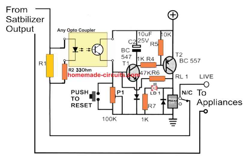
Calculate R1 in the following manner:
R1 (Ohms) = 1 / Max current limit (Amps)
Wattage = 1 x Max current limit
Thanks for your update, and here I am. In my last comments I raised my doubts and you directed me here. As comparing main article’s diagram, this one looks more promising. However after observing the relay contacts I have yet some more concerns:
1). I think In some other post, I read about HYSTERESIS, how it is handled in this circuit. In case the HYSTERESIS is still a problem then IC based circuit shall resolve it or just the transistor circuit as above.2). If for some reason i.e. the power to above circuit is not working etc. the circuit may turn on the load but Overload protection may remain absent. Is it possible to make it work the opposite way i.e. Appliance in Normally Open contacts of the relay so circuit Must Turn On to enable the load. In this case if something is wrong with circuit so default state for load is to be off.
3). Do you have something similar in solid state form. Powered directly from 220v and doing the above as well?
4). Am I right about the R1 being a steel wire resistor? Is it available ready made or I have to work it out myself?
5). Is it possible to keep the calculated resistor to a fixed load i.e. 100 watts and change circuit in a way so it can trip for 10, 50 or 100 watt without changing resistor.
Thanks for your patience and help.
Regards
Thank you for posting your questions here.
1) The HYSTERESIS aspect may not be relevant here, because when an over current situation is detected the relay and the circuit get latched, and remain in the latched position until the circuit is reset manually.
2) That’s a good point and can be solved easily with some minor modifications in the design. For this, the positions of the opto-coupler and the push-button/P1 need to be swapped with each other. The P1 actually can be entirely removed with only the push button staying in the new position for initiating the circuit manually. The push button will need to have a series 2.2M resistor for protecting the T1 base.
3) That might be possible by replacing the relay coil with the input of an SSR circuit. You can find a few good SSR circuits in the following post: https://www.homemade-circuits.com/efficient-electronic-relay-ssr-circuit/
4) R1 does not need to be a steel wire, it can any ready made wire wound resistor rated at 20 watt or above.
5) That may be possible by adding a preset control parallel with R1. This preset value can be adjusted to vary the load current threshold for the opto coupler.
Let me know if you have any further questions!
Thanks for all your replies. My current motor is of 50 watts , 220v specs so I calculated Amps as 60w /220v = 0.273 A so R1 resistance is 3.66 Ohm = 1 / 0.273. I calculated with an additional tolerance of 10w thus total as 60W however the resistance seems high and shall dissipate too much heat (around 50w). I may found it as an aluminum body power resistance but during 30 to 40 minutes operation of spinner motor it may get too hot. Is all calculations are right and I have to go through this route? Thanks and regards
Here, for the voltage we have to consider the voltage across the resistor which should be around 2V, for properly illuminating the optocoupler LED.
So, R = 2 / 0.273 = 7.32 Ohms
Power = 2 x 0.273 = 0.546 or maybe 1 watt.
The power rating looks weirdly small but I cannot see anything wrong with the calculations.
If you are not comfortable with 1 watt you can increase it to any other higher value.
Thank you so much for an example as it cleared out all ambiguity and I do remember Ohm’s law as well. Now I clearly understand I can use a germanium transistor for a V = 0.3, or a silicon transistor for V=0.7 etc. and subsequent lowering resistance as well. Moreover I got confused by resistance power rating. I think I can now use a carbon resistance to check this whole idea and in final design a wire wound resistor may suffice. Well let me experiment it on a bread board first. Moreover how do we suggest a fuse rating for a 50 watt 220v washing machine motor, is there any formula? Regards
Thank you Sak, Glad it helped.
let me know how it goes.
Fuse rating is actually quite easy to calculate, for 50 watt 220V, the fuse rating can be:
50 / 220 = 0.227 amps, if we provide slight more margin, it can be rated at 0.250 amps or 250 mA.
OK, since an inductive load was involved so the inrush current. For the sake of completeness and helping some other needy, a complete discussion regarding motor inrush current is available in this article. So suits the overall situation more :
https://www.homemade-circuits.com/mains-over-load-protector-circuit-for/
Regards
Thanks for the suggestion, it looks more appropriate for your application.
Another important importation I was looking for was to suppress arching at relay contacts and I have found it also:
https://www.homemade-circuits.com/prevent-relay-arcing-using-rc-snubber-circuits/
Thanks for all these important building blocks.
Thanks! yes, one of those concepts can be used for suppressing relay arcing.
Dear Swagatam
I have tried to checked the above concept and put a resistance in series with motor and it smoked away (as per above discussion, it was being calculated with a 50 watt motor). I have then checked the spinner motor with Amp meter and my readings are as below:
1): Spinner Motor without any Load:
==========================
1.2 to 1.2 Ampere as startup and after 1 second keeps fluctuating and after 8 seconds settles down to 0.75 Amps
2): Spinner Motor with Load:
====================
Startup 1.3Amps and immediately settles down to 1.2 Ampere and stays there (measured for 8 seconds).
With above facts my new calculated resistance should be R=1.5Ohm with V=2 and Amp = 1.3. My problem is that there is very slight difference between 1.3 Amp to 1.2 Amp or 1.1 Amp.
Q.1)-The voltage drop remains enough to illuminate an LED whether its 1.2 or 1.3 Ampere? Circuit should turn off in either case, how to correct it?
Q.2)-Since resistance is fixed at 1.5 Ohm then as per calculation, if Ampere goes down then resistance value is changed as well in formula but in real world with a fixed resistance how does it behave?
Regards
Hi Sak,
Which type of resistor did you use. You must use a wire-wound resistor which will never smoke.
Also, if the motor starts with a high current initially and then drops to a lower value, then that is again a problem, because the circuit will trip at the start up. In that case we have to bypass the resistor for a few seconds during start up.
Since opto coupler sensor is not very accurate so the cut off cannot precisely be be at a fixed current, there may be some variations.
If you don’t want a fixed resistor as the sensor, you can add a rotary switch with multiple calculated resistors and then select the appropriate resistor as per the load current.
Q1.”The voltage drop remains enough to illuminate an LED whether its 1.2 or 1.3 Ampere?”
Ans. LED brightness will vary according to the varying current. At 1.2A the brightness might be dim which might increase at 1.3A. At what point the circuit trips that must be verified with experimentation.
“Circuit should turn off in either case, how to correct it?”
Ans: Circuit will trip only when the LED brightness is just sufficient to switch ON the circuit and this cut-off threshold would be approximately fixed.
Q.2)-“Since resistance is fixed at 1.5 Ohm then as per calculation, if Ampere goes down then resistance value is changed as well in formula but in real world with a fixed resistance how does it behave?”
Ans: With one fixed resistor you can have the cut off only for a particular current level. If you want the cut off at different current levels then you may have to use a selector switch to select different resistors.
Thanks Swagatam. Great explanation.
My pleasure, Sak.
PS: After answering my earlier question, I have one more question. as per stated motor ampere facts, what should be the overloading ampere cut off i.e. 1.5, 1.6 or 2 ampere? Do some kind of theory exists for that as well?
It depends on the motor current specifications. The overload current can be around 20% more current than the normal current rating of the motor.
Dear Swagatam,
I have observed that many AC motors have a centrifugal switch which is used to disconnect the capacitor + motor running coil after motor’s shaft have some momentum built however I have observed that Spinner/ Dryer 50W motor has no such switch? It is stated that in AC motors if this particular switch does not open the contact switch then continuous power to running coil burns it. What spinner motor has no such switch? Thanks and Regards
Thank you Sak, for the interesting information.
Yes, you may be correct. However I cannot confirm this, because I do not have sufficient knowledge of centrifugal switches.
Ok, I have found out that there are different types of AC motors and perhaps my motor is “Permanent Split Capacitor (PSC) Motor” which does not need a centrifugal switch. Am i right? regards
That’s correct Sak,
A permanent split capacitor (PSC) motor does not require a switch because it has a permanently connected capacitor that is always in the circuit.
Thank you!
Hello sir , have a nice day ,
Sir I need a circuit diagram for Overload , No load protection for 1 hp submercible Motor . used by current transformer .
thanking you .
with regards ,
Mohamed farook .
Hello Mohamed, if possible I will to design it and post it here:
Operating supply is 12v think, coz not define in schematic.
yes can be 12V or 6V depending on the relay coil voltage
Dear sir,
Please sir, help me with an Ac circuit that can protect 220V Ac led bulbs, flat screen Tv etc from over voltage/current condition from the Mains supply.
Godfrey, for this you will have to install a voltage stabilizer unit which can regulate the voltage for the loads. Or you can also build an over voltage cut off circuit as explained in the following article:
https://www.homemade-circuits.com/highly-accurate-mains-high-and-low/
Okay sir
Thank you very much
What can I do to reduce the electricity bill?
Use LED bulbs for all the lamps and reduce the fridge setting to minimum, don’t use geyser too often.
Hi,
Is it possible to build a mosfet based circuit with a gate driver ic, that cuts off the mains ac at 250V (between line and neutral) and doesn’t let it build to to the 350V peak and then again reconnect the circuit when the voltage falls below 250V and vice versa in the bottom half of the cycle?
This circuit will feed a diode bridge and capacitor and motor driven by pwm motor driver ic. The motor driver ic output igbt often fails short at 350V, so I want to reduce the peak voltage across the diode bridge and capacitor to 250V. A transformer might solve the problem, but if input mains voltage goes too low, then motor may burn out due to high currents.
Instead of unregulated mains ac, regulated ac at 180V or regulated dc at 250V would be very helpful. Total power required is around 500W. Inrush filter is already present in the circuit. Can only tinker with the input to the existing pcb. It will be too complex to redesign the pcb.
I am open to any other design as well. Thanks.
I think regulating the DC side would be less complicated than controlling the AC peaks.
So, yes that’s possible using a simple linear MOSFET regulator as explained in the following article.
https://www.homemade-circuits.com/0-300v-variable-voltage-current/