The post presents a simple Li-ion emergency light circuit with over charge and low battery cut off features. The Circuit was requested by Mr. Saeed Abu and Y0f4N.
Technical Requirement
My requirement is:(1) Circuit is Operated by Nokia standard cell phone charger
(2) Battery nokia 3.7 volt
(3) Auto ac to dc changeover system when ac fail
(4) Battery overcharge protection system(auto battery full charge cutoff) with LED indicator.I have tried many times to develop such type of circuit but i failed. So Please bro help me urgently. Please design it simple.
The Design
The proposed Li-ion emergency light circuit with over charge and low battery cut off features functioning may be understood with the the following points:
Transistor T6 is basically configured to automatically sense and shut off the LED during the presence of mains AC and vice versa. Here a mobile charger is used for powering the T6 circuit.
As long as the mains input is available, the 1 watt LED stays switched OFF due to the presence of a positive potential at the base of T6, T6 starts conducting the moment AC mains fails illuminating the connected LED with the help of the attached Li-ion battery power.
T1 and T2 form the low battery detector stage and does the same when the Li-ion battery voltage falls below a certain predetermined level set by P1.
When this happens, T1 just stops conducting forcing T2, T3 to switch ON hard.
T3 passes the battery voltage to the base of T6 choking its conduction thereby shutting off the LED and inhibiting any further loss of voltage under the situation.
T4 and T5 are configured for the opposite function, that is for detecting the full charge of the li-ion battery.
P2 is appropriately set such that T4 conducts fully at this battery voltage.
With T4 fully ON, the base of T5 is unable to acquire the required negative biasing via R6 and thus is prevented from supplying the charging voltage to the battery, which in turn protects the battery from getting over charged and damaged in due course of time.
The red/green LEDs indicate the relevant states of the battery and the cut off conditions.
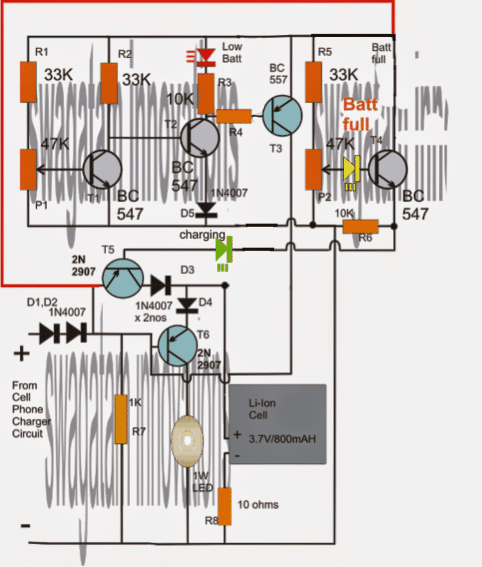
The 10 ohm with the negative of the battery may be eliminated, it's not worth with so many existing protections.
For getting a better response from the over-charge cut-off stage, the above circuit could be modified further with an additional transistor stage T5, as shown below:
Referring to the following circuit, we are able to the see a few crucial additions and removals:
IC 7805 has been added, diode at T6 collector is removed, and D1 position changed. These changes ensure that an exact 4.3V is able to develop across the emitter of T6 and ground, irrespective of the input voltage level.
D5 has been removed in order to provide a better illumination for the LED at the collector of T2.
All high value resistors have now been reduced to 1K for an increased current biasing for the BJTs.
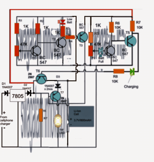
As suggested by one of the avid readers of this blog Mr. Syed, the above diagram needed some corrections.
The finalized diagram of the Li-ion emergency light circuit with over charge and low battery cut off featurescan be seen below:
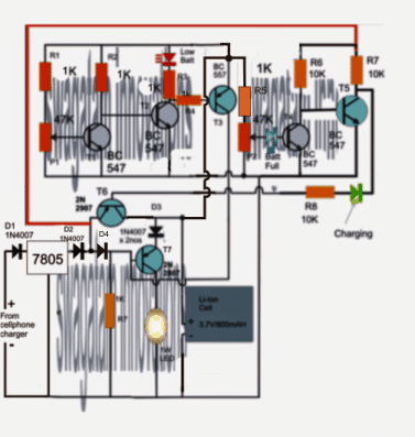


Questions & Answers
Hello Swagatam,
thank you for your fast design.this design more cheap and easy to find for componen at local store.I just modify for LED driver with replacing T6 with BD 139 and adjust R7 with 10 K for 3 Watt. In this design better you remove D1,D2 as T5 already protected the battery. A
P1 is key to prevent battery to drop to deep and P2 to protect battery from overload.
Just suggestion for protection battery , when we set 3.2 volt as cutt off battery and full charge about 4.1 Volt, then we can modify P1 and P2 as fixed resistor. as I see R1,P1 and R5,P2 are voltage devider.may be it's not easy to find match resistor
Thanks & Rgds,
Yofan
Helo Yofan,
You are welcome!
yes, after confirming the exact values, P1/P2 may be appropriately replaced with fixed resistors..it won't be much difficult
Hello Swagatam,
I just want add some detail for your article at first circuit since use variable resistor. For expert will be no issue to adjusting P1 and P2. As your blog mention, we are here for learning an discussion.
To setup P1 as use for protection low batt
– Remove / unplug the input power supply then connect your low battery (can use 3.2 V or 3.0 V) for me prefer 3.2 V.
– Adjust P1 until red LED was glow and main LED was off
To Setup P2 as use for protection overcharge
– Plugin the input with power supply and put batt with full charge. let say about 3.7 V
– Adjust P2 until green LED are glow
hope this can help
Thanks & Rgds,
Yofan
Hello Yofan,
That's perfect. You've made life easier for those who would want to build this.
Thanks very much.
yofan, the full charge threshold of 3.7 li-ion is 4.2V
Hello Swagatam,
agree with you 4.2 V ..it's seem I miss set to 3.7 V
Swagatam,
What modification should I do in this circuit to support 4 rechargeable pencil cells of 1.2 volts each, at 1000mah. thanks this will be tried out soon, what can i use as the equivalent of BC 547 available.
Regards
Gopal
Gopal, No changes would be required, you may use the same configuration.
any general purpose NPN transistor will work in place of BC547
Hello sir,
Just I wana to make a circuit wich work in such a way that when ac supply is off then dc supply automatically on but when ac supply is on then dc supply automatically off.pls reply me sir ….
Trilokee, pls refer to the following article, you can use the transistor stage for your application:
https://www.homemade-circuits.com/2011/12/how-to-make-efficient-led-emergency.html
Swagatam bro hi… maine 3 watt led lagai but transitor hit ho raha h then whai do plz help me
bro use 1 watt led, not 3 watt led, for 3 watt use tip127 as the transistor and a 3.7/2ah batt
Bro thanks for ur developing my requesting circuit and also ur so talent on electronics.If i use 5/6 cell in parallel then this circuit will work properly?What is the alternative transistor of 2N 2907?
my pleasure bro, you can use a TIP127 for 5/6 cells.
but please note that the circuit is not yet tested by me, although i believe it would work
Bro thanks ur reply.Where should i use TIP127 for 5/6 cells(Parallel connection) in above circuit?Also any change is required in Charge section in above circuit for 5/6 cells(Parallel connection) ?
TIP127 should be replaced for the 2N2907 transistor.
no other changes would be required.
what is R4 value?
10k
Bro What is the R3 and R4 value?
bro, both are 10k
Bro what is value of R3 and R4? Is R8 is essential for this circuit?
R8 may be removed
bro is R7=1k is needed and why? Also i can not collect TIP 127 in my locality.So am i use BD 140 or any other NPN Transistor?
Bro R7 is for enabling the transistor to conduct when mains is absent, without it the LED will not glow.
BD140 will do, it's not an NPN, rather a PNP
Bro thanks ur reply.However today i have developed ur circuit as per ur given model and i successfully done auto ac to dc changeover system,battery low voltage cutoff system but i can not success in auto high voltage cutoff(battery over charge protection) system.The problem is here:
1)The green LED is not glow during battery voltage is 4.25 when charger is connected but when charger is disconnected from circuit then green LED is glow but so dim.
2)Then i replace R6 into 1k then green LED is glow normally.
3) I tune P2 very accurately at battery voltage 4.25 but auto high voltage cutoff(battery over charge protection) system is not worked.
4) Only working Battery's self overcharge protection circuit when voltage raised at 4.25v but not ur given over charge protection circuit that's why the green LED is not glowing.
5) I have tested it by connecting a battery without it's self overcharge protection circuit with ur circuit.Ur circuit is continued to give charge that battery and battery voltage is raised up to around 4.75 then i stop to give charge my battery.
So bro it seems to me that in auto high voltage cutoff(battery over charge protection) system there is something wrong.Pls refine it.This circuit is badly needed for me.I have tried to refine it but i failed.
Bro, remove the green LED from the shown position, and connect the collector of T4 to directly to positive.
Now connect the green LED in series with the base of T5, anode to base, cathode to T4 emitter.
When the voltage reaches 4.25V, this LED will shutoff indicating that T5 has been switched OFF and the battery is receiving no charging voltage.
….also reduce R5 to 1K
please try this and let meknow the results.
Bro then what will be the P2 condition it will be removed or not?
everything else will be as before, even the setting of P2
Bro i have tried again as per ur modification guideline but result is not positive.The green LED is not glowing during charging the battery so there is no question of shutoff the green LED When the voltage reaches 4.25V.Also ur developed auto high voltage cutoff circuit (battery over charge protection) system is not working.Only working Battery's self overcharge protection circuit when voltage reaches at 4.25v( I have tested it again by connecting a battery without it's self overcharge protection circuit) .So Bro i think u have to redesign the circuit freshly and upload it again.I am waiting for ur great feedback.
Bro, electronics is not easy, you won't get results even from the easiest of the circuits until you do it by understanding it.
The above circuit is perfect in all respects according to me, however if you can pinpoint the faults in the design then surely we can debate on that.
Alternatively you can try testing the design by checking the voltages at the base of T5 while setting P2. The base voltage should almost become zero at 4.25V.
confirm this by disconnecting the emitter of T4, this should revert the T5 into conducting mode again. once confirmed connect it back in position.
…check it by putting red prod of the meter on the positive line and black on the base.
when conducting, it should show near 0.6V, keep adjusting P2 until it drops to zero at 4.25V.
also replace all 33k resistors with 1k resistors.
Dear Sir,
I request you to kindly suggest me a simple circuit to cut off power supply to a 4V-4Ah lead acid battery on full charge (over charging protection) from a 5V mobile charger.
Dear Vidyarthi,
you can use the following design
https://www.homemade-circuits.com/2013/12/make-this-usb-li-ion-37v-battery.html
sorry here's the correct link:
https://www.homemade-circuits.com/2013/12/usb-automatic-li-ion-battery-charger.html
Dear bro, I have tried again as per ur latest direction but i am again failure.here the problems are:
1)The voltages at the base of T5 cannot make zero from 0.6v by setting up P2.
2) The green LED keep glow gently at 4.25v of the battery.
3)Also ur developed auto high voltage cutoff circuit (battery over charge protection) system is not working.Only working Battery's self overcharge protection circuit when voltage reaches at 4.25v( I have tested it again by connecting a battery without it's self overcharge protection circuit).
4)But ur other system low battery cutoff and ac to dc change over system is ok.
So bro what can i do now to over come above problem.Please do something.I think u should practically make this circuit then u can easily find out the problem.
Dear Bro, I have modified the diagram with an additional stage, please do it as per the new diagram and check the response.
Dear bro i have tried again ur new circuit as per ur direction but no positive result.The problem is here:
1) The charging green LED is glowing during charging but no so much glow.
2)The yellow LED is not glow during battery voltage is 4.25 also i can not glow that by adjusting the P2. At 4.25v the voltage remain in yellow LED is approx. 0.65v.
3)Also ur developed auto high voltage cutoff circuit (battery over charge protection) system is not working.Only working Battery's self overcharge protection circuit when voltage reaches at 4.25v( I have tested it again by connecting a battery without it's self overcharge protection circuit, it getting charged 4.40v then i disconnect the charger).
4)But ur other system low battery cutoff and ac to dc change over system is ok.
Bro what will be the solution of this.I think u have to develop this circuit practically to find out the solution of this.
Dear bro, the second circuit is perfect in every way.
again I'll say if you do without understanding, you will keep getting problems.
if T4 and the yellow led are not conducting it means either one of them is faulty or the connections are wrong in your circuit.
make R5 = 1k (I had suggested this before also)… and check.
as soon as T4 conducts, T5 will switch OFF and the green LED will also switch OFF
you can try making the series resistor of green LED to 1k for increasing its current and brightness.
practical making won't be required because I am sure this circuit is OK.
…bro, i think got the culprit.
the yellow led should not be placed at the emitter of T4. connect the emitter of T4 directly with ground
put it at the base of T4….and check.
the emitter position is not allowing T5 to stop conducting completely.
I'll correct the diagram soon.
Pls bro correct the diagram ASAP.I am waiting for this.Also i need true over charge cut off system i mean battery will be over charge cut off by ur circuit not his(battery) self over charge circuit.
Thanks bro I'll wait for ur corrected diagram also i need true over charge cut off circuit which only worked by ur developed circuit not by the battery's self over charge protection circuit.Pls bro update ur circuit ASAP.
Thanks bro, I updated it yesterday itself….please check it out.
Dear bro, i have tried again ur revised circuit but problem is still exist, these r:
1)Ur developed Over charge cut off system is not worked only work in case of battery with self over charge protection circuit which i have told u before.
2)During low cut off and Over charge cut off stage the charging Green LED is glowing gently (when i disconnect the charger.)
3)During over charge cut off stage the full charge indicator Yellow LED is glowing gently.If i adjust the P2 to increase the brightness of Yellow LED then Green LED glow gently and vice versa.
So i am hoping a nice solution of it from u.
Sorry Bro, that looks impossible…
If the blue LEd in the last diagram illuminates it means T4 is conducting.
If T4 is conducting it would ground the base of T5, stopping it from conducting.
When T5 is stopped from conducting how will the green LEd glow???
Because as long as T5 is conducting the green LED is getting its ground through the collector/emitter of T5, once T5 stops conducting this passage is blocked and the green LED also has to stop glowing, resulting in shutting off the 2N2907 transistor completely.
Check the voltage at the base of T5 when the BLUE LED is glowing. It should be zero and the green LED must stop glowing.
Please do the above, we'll troubleshoot it right here…..
…i did a slight change in the diagram please check it.
1 watt led glow dim can i remove 10 ohm and how to check battery charging or not
yes you can remove the 10ohm resistor.
the green LED indicates battery is charging.
When charger connect green led not glowing
I remove 10ohm resister but led glow dim
the presets will need to be correctly adjusted to get a proper response from the circuit.
Can i use 2 battery in parallel any change make
no changes will be required.
Sir, please add LDR circuit for LED on when night if day light mains power goan LED OFF only night time LED on
OK, I'll try to include it.
Sir, charging volt show 3.68 battery postive between D3 & D4
try only one diode at the input, D1 or D2, remove one of them and check the response
Sir plz tell 2N2907 pinout i confused. and any eqvalant
the lead which is close to the small body projection is emitter, center lead is base, the last one is the collector
1.bp.blogspot.com/-TAriua1lYrg/TyuESv5W6XI/AAAAAAAAA1s/tgwVOMmoAdA/s1600/2n2222.png
My battery can not charge above 3.96v. i use mobile battery charger is it correct.? 2N2907 eqvalant or can i use 2N2222 ? I know 2N2907 matal pinout but i want to plastic transistor pinout
2N2222 is NPN, not PNP…. moreover it's also a metal can transistor.
you may use use 8550, or BEL188, or BD140
Bro i go through ur two updated circuit diagram but no positive feedback.At first u have to clear me that ur given circuit is capable for true over charge cut off feature because i have seen that it is only depend on battery's self over charge protection circuit which i have told before many times.If this circuit not then what about this Circuit(https://www.homemade-circuits.com/2013/12/usb-automatic-li-ion-battery-charger.html). Can i use this for my same requested purpose?
Bro, i did not understand what you are saying.
are you using the above circuit with another auto-cut off circuit??
If it is so then you should remove it and use it only with a simple 5V adapter.
I suggested you to measure the voltage at the base of T4 while adjusting P2, but you did not do so.
The above circuit will surely work if it's done as per the rules, not by trial and error.
anyway you can try the other one which you have asked, but if you could not make this one you wouldn't be able to make that even, because it has a opamp which will require even more knowledge and precise adjustments.
My battery can not charge above 3.96v. i use mobile battery charger is it correct.
Plz i want mobile battery charger circuit operat on ac 230 v
https://www.homemade-circuits.com/2014/02/220v-smps-cell-phone-charger-circuit.html
Blue LED glow so dim
Bro i mean that the over charged cut off feature of above circuits will work if i connect a battery without it's self over charged protection circuit(circuit which remain on the top of mobile battery) or 4.2v dry cell battery? Please confirm it first then i will share the other problem oh these circuit.
Bro, do you mean the batteries have its own built-in overcharge protection? I have never heard of this before, can you show me an article or image which explains this??
Dear bro no need to show any article / image to prove this u can easily prove it by yourself.At first:
1)U have to take a Nokia Battery and a Standard Charger.
2)Now u simply charge that battery with that charger directly(no use any circuit, just join the anion and cation of the charger directly to the battery anion and cation section).
3)Wait for the voltage reached at 4.24v of the battery and then connect digital meter on the battery to see the voltage in charging condition.
4)U will see when voltage reached 4.25v of that battery then it stop to take the charge automatically and the voltage suddenly increased approx. 6.5v to 7.5v which mean that the battery did not take any charge.
5) Now u remove the top built in circuit of that battery carefully.U will find Anion and cation section and connect to the charger accordingly.Then u have to do same experiment according to my above way.
6)At last u will share the result of this experiment ASAP.
Dear bro, that's a wrong impression you have got, if it works in that way then why do you need an overcharge protection in the above circuit?
If you continue doing in that way, your battery could bulge after some days and start leaking or even explode.
The following is the last and final adjustment that I am presenting for the last circuit.
Without connecting any battery first make sure the voltage at T6 emitter and ground is 4.2V.
At this position (without any battery connected) slowly adjust P2 until just the green LED shuts off or becomes too dim.
Your circuit is set now, after this you may connect the battery for getting the required over charge cut-off at 4.2V
If you find all these difficult there are much sophisticated circuits as given under, you can try them out:
https://www.homemade-circuits.com/2012/12/li-ion-battery-charger-circuit-using-ic.html
https://www.homemade-circuits.com/2012/05/make-this-li-ion-battery-charger.html
Dear bro i have done many experiment on Cell phone battery last 3 to 4 years and still doing.Also i have discussed about it so many mobile technician in my locality.In that way i am running many project by cell phone battery but no problem is raised.So before comments on my experiment u have to do that experiment practically.I hope u will do that and give me feedback ASAP.Also u asked me why do i need an overcharge protection in the above circuit? Because i need a fully automatic feature like Inverter.That built in circuit of battery only covered over charge feature but not covered low cut off and ac to dc change over feature.However i will check that circuit again also ur two new link.i will wait for ur that experiment which i have told u bro.
sorry bro, no battery has such a feature, especially with li-ion batteries we need to follow strict procedures while charging so that they don't get ruined soon and to prolong their working capacity. therefore Li-ion batts are always charged using sophisticated chargers.
Dear bro r u saying me that by doing that experiment or not? If not then do it then challenge me that was my wrong experiment.In addition, i have made many times for my many project full charge indication by zener diode using cell phone battery's self over charged protection system feature. So please do that experiment as per my direction.
Dear Bro, any battery will stop taking charge after the voltage reaches its maximum charging capacity but that doesn't mean you can keep the charging switched ON…because that would force the chemical reactions to continue inside the cell and start damaging it slowly.
I'll advise that you should first research online how to charge Li-ion batteries before getting so much confident.
Dear Bro we call that circuit is PCM=Protection Circuit Module.However u can go through these link:
1)www.master-instruments.com.au/related_info/PCMs%20for%20Lithium%20Ion/PCMs%20MI%20Offer%20for%20Lithium%20Ion%20and%20Lithium%20Polymer%20batteries.htm
2)www.slideshare.net/pettersss/about-cell-phone-batteries-use-common-sense-and-charging-techniques
Which will encourage u to do that experiment.
Also ur comment ''any battery will stop taking charge after the voltage reaches its maximum charging capacity'' is totally wrong because i have charged a battery with PCM up to 4.25v then it stop to take charge(In that situation the voltage was around 6.5 to 7.5v at the battery with connecting the charger, i have checked it by Digital meter)then i take the same battery removing the PCM it is now charging upto 4.4v and continue to charged and i stop it for explosion risk.
Now explain me how can differ the full charge voltage between The Battery with PCM and the same battery without PCM???
Dear bro, right at the beginning I had asked you provide a link regarding this and you said that no link was required because you had tested it practically. however I wanted to believe it only through reliable source and not your experiments, since now you have provided it now it's very clear what you meant to say.
Now it makes sense, and it also proves that how sensitive Li-ion batteries are and without a strict charging circuit it could explode or start leaking.
By the way all Li-ion batteries may not have this built-in protection that's why an external protection is required.
I did not want to say that ''any battery will stop taking charge after the voltage reaches its maximum charging capacity'' but since you were not agreeing and proving your experiment to be correct without any reliable article by saying that your cell was not taking above 4,25V so I had no choice but to say this. I know that a battery may keep charging to dangerous levels and that's why protection circuit is imperative.
Still I did not understand your last question.
My above circuit can be set to any desired cut-off level, you can set it to cut off before the PCM level or the same level….but the PCM will have no connection with the above circuit, they are independent and will not read and react to each others conditions.
…..the above circuit will cut-off at the same level every time with PCM or without PCM it won't make any difference. If it's set to cut off at 4.2V then it will cut-off at this voltage even without the PCM connected.
It's better to test it without a PCM fitted.
The crucial thing is the input voltage at the emitter of T6, which should be 4.3V so that it can cut off at this voltage.
Sir. Any mosquito repellint circuit ac operated
I don't think these circuits really work, mosquitoes cannot be deterred using electrical frequencies
Dear Bro thanks for trusting on my experiment at last.Though i am Pharmacist electronics is my heart. There is no difference between human body and circuit.So i feel it so much.Actually,The PCM makes the Li-Ion battery superior from others.However i am still working on ur given circuit for better outcome.I will give u feedback ASAP.
You are welcome bro, yes surely we are all just like machines too.
By the way with a PCM connected you can simply use a 7805 IC for supplying the Li-ion cell, it'll do the job perfectly, no other additional circuits would be required….for getting an LED indication, you may use a few of the above circuit stages
Sir your 1 watt led emargency ac operated circuit . I can under stand BT136 pinout in data sheet there show M1 M2 G . In our city 100uf/225v not aveliable can i use 100uf/160v. And 2uf/400v is it 205/400v ?
Ravindra, don't make the circuit using SCR or triac it could be a lot difficult for you, instead you can try the following:
2.bp.blogspot.com/-nKF8T8lKIxY/UMg7YDLNQ3I/AAAAAAAAB8U/S1OWTK0cMD4/s1600/Surge+free+transformerless+1+watt+LED+driver+circuit.png
Thanku for replay but above link there is no battery for emergency for mains fail
the SCR circuit which you are presently building also does not have an emergency feature, my suggestion was with reference to the SCR circuit not the above.
which circuit are you referring to?
https://www.homemade-circuits.com/2013/04/1-watt-led-emergency-lamp-circuit-using.html?m=1 in this circuit
bro u above 2 circuit the battery get charged max. 3.90v.Also with PCM the full charge auto cut off is occurred but no full charged indication by LED. Without PCM no full charge auto cut off is occurred also no full charged indication by LED. However, ur other feature is ok. Bro i think u can add 6v dc relay to fix the problem.Is it possible?
sorry bro with this circuit a relay cannot be used, we'll have to go for an opamp circuit for operating a relay….
I am 100% sure about the above circuit that it will work just needs to be tweaked by observing the base voltage T5/T6 with a multimeter while adjusting P2.
unless its not done with a multimeter, the results cannot be confirmed
If the LEDs are not glowing properly we can change their positions, no issues, but the important thing is to make sure that the base of T6 becomes equal to its emitter voltage when the battery voltage reaches 4.2V
And for this to happen the input voltage at the emitter of T6 should be precisely 4.2V, if it's more T6 will never shut off.
Bro i can not get ur point properly.What will be the base voltage of T5/T6 when battery get its full charge?Pls describe it properly so that i can examine this properly.
Bro, base of T5 should become zero or near zero at 4.2V, this will force the base of T6 to become 4,2V or near 4.2V….all these should be measured with respect to ground or negative of the supply, while P2 is being adjusted.
You can do it in the following manner:
Without connecting any battery first make sure the voltage at T6 emitter and ground is 4.2V.
At this position (without any battery connected) slowly adjust P2 until just the green LED shuts off or becomes too dim.
Your circuit is set now, after this you may connect the battery for getting the required over charge cut-off at 4.2V
make all the LEDs to red for better response.
,,,,bro, I have made one small change in the above circuits to ensure a better response.
the upper circuit is now supplied from the emitter of T6, and not from the battery….see the red line it joins with the positive line of the upper circuit.
also due to the presence of D3 please make sure that the charging voltage from the source at emitter of T6 should be 4.2 + 0.6 = 4.8V this will produce a correct charging voltage of 4.2V for the Li-ion battery after passing the drop through D3.
Hello sir i have made this circuit..
i want to ask that the circuit will perform well on this configuration.
i have used tip127 so can i use led upto 5a??but i am using led of 0.6a with 4v 1.2a battery..Battery is not Li-ion battery.
Hello Syed, yes it will work, but with a 600mA LEd your battery will become flat quickly, you will need a minimum 4AH battery for getting around 3 to 4 hour backup
Ok sir,
but i am in trouble with P1, But i have adjusted P2 ..
i have seen the above the comment for adjusting this but when i attach a weak battery of about 3.0 volts and adjust the P1 the Red Led does not glow properly but it glow.and my Main Led(600mA) does not Off..
You can change the series 10k resistor to 1K and see the response, it should brighten up the LED…
sorry, i could not understand your last question…." but it glow.and my Main Led(600mA) does not Off".
…OK got it now, you mean to say at low voltage, the emergency 1 watt LED lamp does not shut off fully
what did you use for R4?
use 1k resistor for R4 and check the response
Sir. I want to ask about the adjustment of P1 and P1 .
When i connect a weak battery and adjust the P1 the red led(low batt) does not glow at any point.i have the reduced the value of the resistor connected with Low battery led.but it was not glowing and when i connect the charger it glows..
if the charger has output of 9 or 12v volts, will it effect the components?
For P2 when i connect full charge battery and charger to adjust, and after adjusting it in that position when the Blue led(full batt) glows i change the battery with weaker once but the led is still glowing.. (O_o) .i have check all the connection these are perfect..
Please describe the adjustment of P1 and P2 .