• Skip to main content
  • Skip to primary sidebar

Homemade Circuit Projects

Need circuit help? Post them in the comments! I've answered over 50,000!

Blog | Categories | About | Contact | Calculators-online
You are here: Home / Sensors and Detectors / Knock Activated Door Security Intercom Circuit

DIY Circuits | Learn Basics | Arduino Coding


Knock Activated Door Security Intercom Circuit

Last Updated on March 21, 2019 by Swagatam 3 Comments

In this post I have explained a simple knock activated door security alarm circuit which can be installed by anybody for identifying a guest or an intruder at the door. The idea was requested by Mr. Akhilesh.

Circuit Objectives and Requirements

My brother is trying to prepare a project for his college is “Speaker intercom phone”. When visitors knock door (or ring bell) I can talk to him without open door.I found many circuit on online be none of any solved my purpose.The key point in project is :

1:- No need of door bell.

2:- No any switch for guest to talk (switch is for me only).

3:- Only mic and speaker at visitor side, reducing cost its chance to theft the circuit. in this cars lose is

very less and easy to repair. 

If any circuit (DIY) is available or design for me.

Please confirm its price and detail how to buy it.

The Design

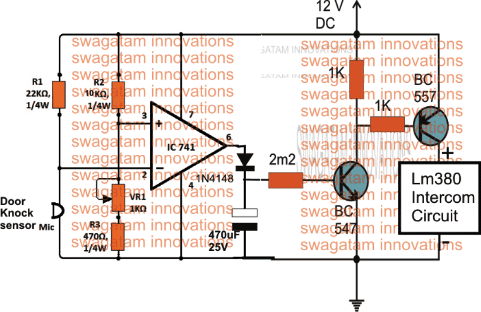
A simple knock activated door security intercom circuit is shown in the above figure.

An opamp using IC 741 is used as an amplifier, while an electret MIC is used as the door knock sensor.

The MIC is supposed to be glued with the door inner surface so that whenever the door is knocked from the other side the mic is able to sense the corresponding vibrations.

Each knock vibration sensed by the MIC is converted into electrical negative pulses, which momentarily ground the inverting pin#2 of the opamp which can be seen attached with the MIC and the associated biasing resisting R1.

This resistor value can be altered to change the sensitivity of the MIC reception.

The above action is amplified by the opamp to produce equivalent pulses as high as the applied supply voltage at its pin#6.

The next stage  which may be seen integrated with the output pin#6 of the opamp is simple transistor delay timer circuit, which responds to the opamp high output pulses and generates sustained delay OFF output at the collector of the PNP transistor BC557.

Meaning whenever somebody knocks at the door the MIC senses it and activates the opamp to create corresponding short high pulses at its output pin#6 which is held and sustained for a few a minutes by the delay circuit.

The delay length can be varied by increasing or decreasing the 470uF/2M2 components either individually or together.

2-Way Intercom System

The sustained delay OFF output from the PNP transistor is used for powering a simple dual speaker intercom using the IC LM380.

This simple 2 way intercom system circuit has been comprehensively explained in one of my earlier posts.

As soon as this simple intercom is activated, the user is able to talk with the guest (or intruder) from inside the house and identify the person before opening the door.

The referred intercom circuit in the link has the feature of a using the speakers on both sides a MIC as well as a loudspeaker for reproducing speech. This is toggled in the talk mode or listen mode through a DPDT switch.

This switch may be controlled by the user while negotiating with the person outside the door, and switchover its position accordingly while talking or listening to the conversation.

For further inquiry regarding this simple knock activated door security intercom circuit, please feel free to express your thoughts through your comments.

You'll also like:

  • delay effect5 Simple Motion Detector Circuits using PIR
  • T and R 40 kHz ultrasonic transducer pair compressedUltrasonic Motion Detector Circuit
  • railway2Bsafety2BlightsFlashing Red, Green Railway Signal Lamp Circuit
  • tiltsensorcircuitTilt Sensor Switch Circuit

Filed Under: Sensors and Detectors Tagged With: Activated, Door, Intercom, Knock, Security

About Swagatam

I am an electronics engineer and doing practical hands-on work from more than 15 years now. Building real circuits, testing them and also making PCB layouts by myself. I really love doing all these things like inventing something new, designing electronics and also helping other people like hobby guys who want to make their own cool circuits at home.

And that is the main reason why I started this website homemade-circuits.com, to share different types of circuit ideas..

If you are having any kind of doubt or question related to circuits then just write down your question in the comment box below, I am like always checking, so I guarantee I will reply you for sure!

Previous Post: « Generator/UPS/Battery Relay Changeover Circuit
Next Post: Make this Radio Repeater Circuit at Home »

Reader Interactions

Comments

Anna says:
June 17, 2016 at 10:56 am

nice

Reply
Akhilesh Prajapati says:
May 18, 2016 at 1:26 pm

Sir,

Thanking you very much to reply. but my purpose has not been solved.

Reply
Swagatam says:
May 18, 2016 at 4:04 pm

Akhilesh, you can try this circuit:

https://www.homemade-circuits.com/2012/08/how-to-make-simplest-intercom-system.html

but it uses speaker instead of mic for speaking

Reply

Need Help? Please Leave a Comment! We value your input—Kindly keep it relevant to the above topic! Cancel reply

Your email address will not be published. Required fields are marked *

Primary Sidebar

circuit simulator image


Subscribe to get New Circuits in your Email


Categories

  • Arduino Projects (93)
  • Audio and Amplifier Projects (133)
  • Automation Projects (17)
  • Automobile Electronics (101)
  • Battery Charger Circuits (85)
  • Datasheets and Components (109)
  • Electronics Theory (149)
  • Energy from Magnets (27)
  • Games and Sports Projects (11)
  • Grid and 3-Phase (20)
  • Health related Projects (27)
  • Home Electrical Circuits (13)
  • Indicator Circuits (16)
  • Inverter Circuits (95)
  • Lamps and Lights (159)
  • Meters and Testers (71)
  • Mini Projects (28)
  • Motor Controller (68)
  • Oscillator Circuits (28)
  • Pets and Pests (15)
  • Power Supply Circuits (91)
  • Remote Control Circuits (50)
  • Renewable Energy (12)
  • Security and Alarm (64)
  • Sensors and Detectors (106)
  • SMPS and Converters (34)
  • Solar Controller Circuits (60)
  • Temperature Controllers (43)
  • Timer and Delay Relay (49)
  • Voltage Control and Protection (42)
  • Water Controller (36)
  • Wireless Circuits (30)


Other Links

  • Privacy Policy
  • Cookie Policy
  • Disclaimer
  • Copyright
  • Videos
  • Sitemap


People also Search

555 Circuits | 741 Circuits | LM324 Circuits | LM338 Circuits | 4017 Circuits | Ultrasonic Projects | SMPS Projects | Christmas Projects | MOSFETs | Radio Circuits | Laser Circuits | PIR Projects |

Social Profiles

  • Twitter
  • YouTube
  • Instagram
  • Pinterest
  • My Facebook-Page
  • Stack Exchange
  • Linkedin


Recent Comments

  • Swagatam on 9 Simple Solar Battery Charger Circuits
  • Gagana on 9 Simple Solar Battery Charger Circuits
  • Swagatam on Arduino 2-Step Programmable Timer Circuit
  • Swagatam on Simple Buck-Boost Converter Circuits Explained
  • Swagatam on IC IR2111 H-Bridge MOSFET, IGBT Driver IC: Full Datasheet, Circuit Diagram

© 2026 · Swagatam Innovations