The proposed infrared or IR remote control circuit can be used to operate an appliance ON/OFF through any standard TV remote control handset.
In this write up I have explained a couple of these simple infrared remote control circuits designed for controlling any given electrical appliance through an ordinary or TV remote control unit.
Introduction
Controlling household electrical gadgets or any electrical equipment remotely can be fun.
Controlling gadgets like a TV set or a DVD player through a remote may look pretty common to us and we are very used to with the experience, however for controlling many other domestic equipment like a water pump, lights etc we are compelled to walk around for implementing the switching.
The article is inspired by our usual TV remote concept and has been applied for controlling other house hold electrical appliances remotely.
The circuit facilitates and helps the user to do the operations without moving an inch from his resting place.
The whole circuit of the proposed IR remote control may be understood by studying the following points:
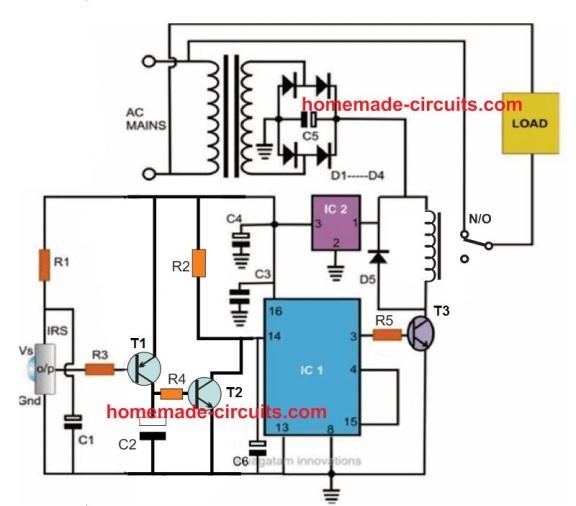
Referring to the figure, we see that the entire layout consists of just a couple of stages viz: the IR sensor stage and the flip flop stage.
Thanks to the highly versatile, miniature IR sensor TSOP1738 which forms the heart of the circuit and directly coverts the received IR waves from the transmitter unit into the relevant logic pulses for feeding the fllip flop stage.
The sensor basically consists of just three leads viz: the input, the output and the biasing voltage input lead. The involvement of only three leads makes the unit very easy to configure into a practical circuit.
The sensor is specified for operating at 5 volts regulated voltage which makes the inclusion of the 7805 IC stage important.
The 5 voltage supply also becomes useful for the flip flop IC 4017 and is appropriately supplied to the relevant stage.
When a IR signal becomes incident over the sensor lens, the inbuilt feature of the unit activates, triggering a sudden drop in its output voltage.
The PNP transistor T1 responds to the negative trigger pulse from the sensor and quickly pulls the positive potential at its emitter to the collector across the resistor R2.
The potential developed across R2 provides a positive logic high to the IC 4017 input pin #14. The IC instantly flips its output and changes it’s polarity.
The transistor T2 accepts the command and switches the relay according to the relevant input provided to its base.
The relay thus switches the connected load across its contacts alternately in response to the subsequent triggers received from the IR transmitter unit.
For the sake of convenience the user may use the existing TV remote control set unit as the transmitter for operating the above explained control circuit.
The referred sensor is well compatible with all normal TV or DVD remote control handset and thus can be appropriately switched through it.
The entire circuit is powered from an ordinary transformer/bridge network and the entire circuit may be housed inside a small plastic box with the relevant wires coming out of the box for the desired connections.
Must Read for you: How to Control Appliances using TV Remote
Circuit Diagram
Video Demonstration
Parts List
The following parts will be required for making the above explained infra red remote control circuit:
- R1 = 100 ohms,
- R3 = 1K,
- R2 = 100K,
- R4, R5 = 10K,
- C1, C2, C4 = 10uF/25V
- C6 = 100uF/25V
- C3 = 0.1uF, CERAMIC,
- C5 = 1000uF/25V,
- T1 = BC557B
- T2, T3 = BC547B,
- ALL DIODES ARE = 1N4007,
- IR SENSOR = TSOP1738 image: Vishay
- IC1 = 4017,
- IC2 = 7805,
- TRANSFORMER = 0-12V/500mA,
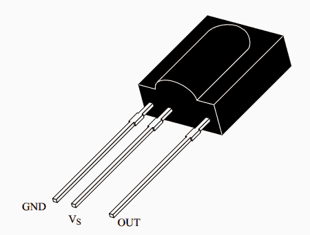
TSOP1738 pinout Details
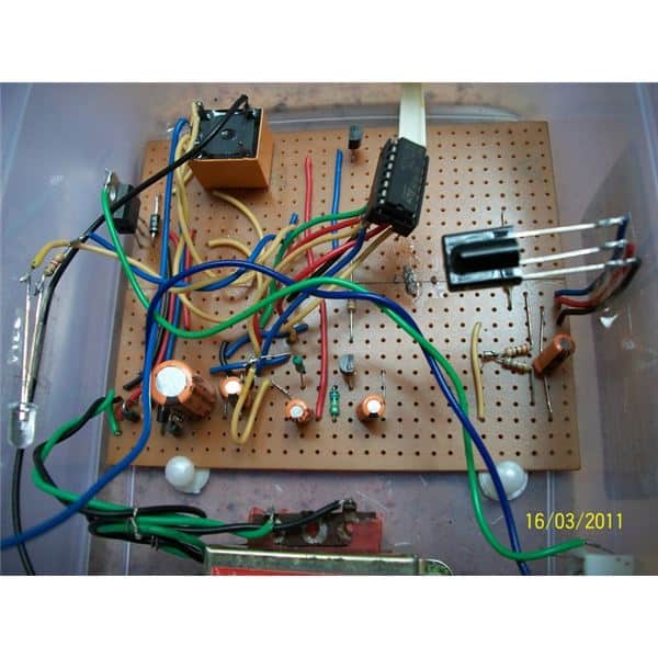
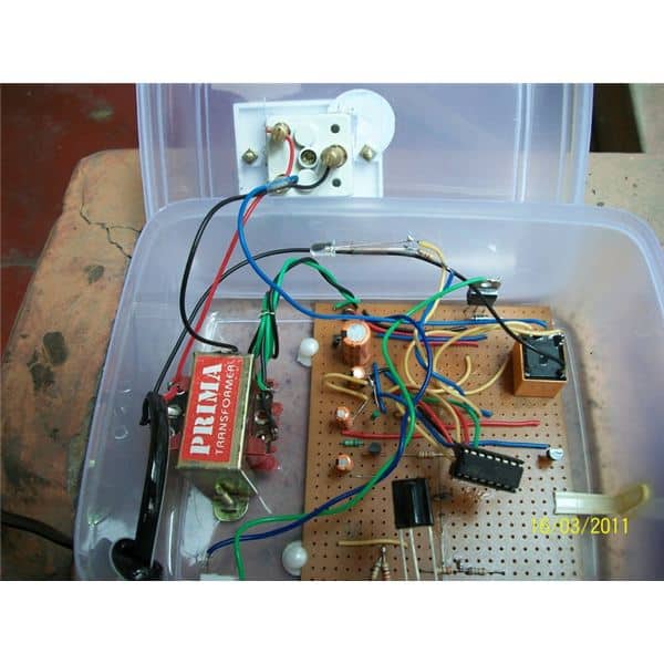
Prototype image courtesy: Raj Mukherji
2) Precision Infrared (IR) Remote Circuit
The second IR remote control circuit discussed below uses a unique frequency and detects only the specified IR frequency from the given remote transmitter unit, making the design entirely failproof, accurate and reliable.
Ordinary IR Remote Drawback
Ordinary IR remote control circuits have one big drawback, they easily get disturbed by stray external frequencies, and thus produce spurious toggling of the load.
In one of previous posts I have discussed a simple IR remote control circuit which operates quite well, however the circuit is not completely immune to external electrical disturbance generations such as from appliance switching etc. which results in false operations of the circuit causing lot of annoyance to the user.
The circuit design included here efficiently overcomes this problem without incorporating complex circuit stages or microcontrollers.
Why LM567 is Used
The solution comes easily due to the inclusion of the versatile IC LM567.
The IC is a precise tone decoder device which can be configured to detect only a specified band of frequency, known as passband frequency.
Frequencies not falling within this range will have no effect on the detection procedures.
Thus the passband frequency of the IC may be set precisely at the frequency generated by the transmitter IR circuit.
Shown below are the Tx (transmitter) and the Rx (receiver) circuits which are set precisely to complement one another.
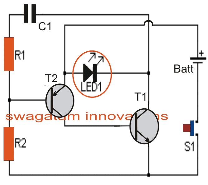
T1 ad T2 along with R1, R2 and C1 in the first Tx circuit forms a simple oscillator stage which oscillates with a frequency determined by the values of R1 and C1.
The IR LED1 is forced to oscillate at this frequency by T1 which results in the transmission of the required IR waves from LED1
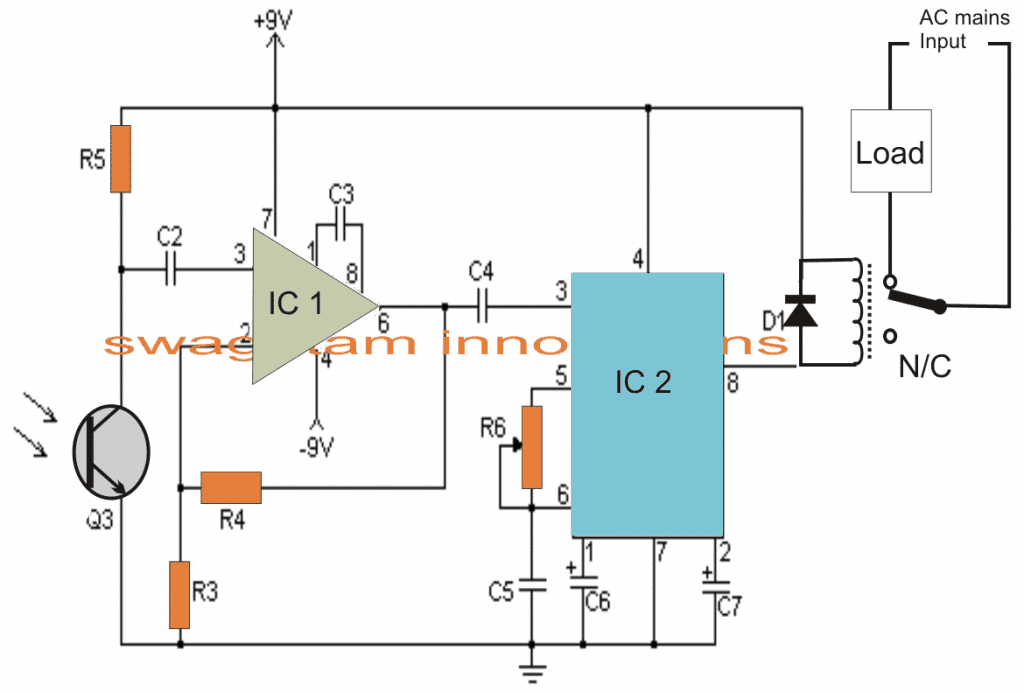
As discussed above, R5 of IC2 in the Rx circuit is adjusted such that its passband frequency precisely matches with that of LED1 transmission output.
Circuit Operation
When the Tx IR waves are allowed to fall over Q3 which is an IR photo transistor, a subsequent order of varying positive pulses is applied to pin#3 of IC, which is basically configured as a comparator.
The above function generates an amplified output at pin#6 of IC1 which in turn gets induced across the input or the sensing pin out of IC2.
IC2 instantly latches on to the accepted passband frequency, and toggles its output at pin#8 to a low logic level, triggering the connected relay, and the preceding load across the relay contacts.
However the load would stay energized only as long as Tx stays switched ON, and would switch OFF the the moment S1 released.
In order to make the output load latch and toggle alternately, a flip flop circuit will need to be employed at pin#8 of IC2.
Parts List
- R1 22K 1/4W Resistor
- R2 1 Meg 1/4W Resistor
- R3 1K 1/4W Resistor
- R4, R5 100K 1/4W Resistor
- R6 50K Pot
- C1, C2 0.01uF 16V Ceramic Disk Capacitor
- C3 100pF 16V Ceramic Disk Capacitor
- C4 0.047uF 16V Ceramic Disk Capacitor
- C5 0.1uF 16V Ceramic Disk Capacitor
- C6 3.3uF 16V Electrolytic Capacitor
- C7 1.5uF 16V Electrolytic Capacitor
- Q1 2N2222 NPN Silicon or Transistor 2N3904
- Q2 2N2907 PNP Silicon Transistor
- Q3 NPN Phototransistor
- D1 1N914 Silicon Diode
- IC1 LM308 Op Amp
- ICIC2 LM567 Tone Decoder
- LED1 Infa-Red LED
- RELAY 6 Volt Relay
- S1 SPST Push Button Switch
- B1 3 Volt Battery Two 1.5V batteries in series
- MISC Board, Sockets For ICs, Knob For R6,
- Battery Holder
Another Simple LM567 based IR Remote Control Circuit
The next accurate LM567 based IR transmitter/receiver circuit ensures that the remote control can be operated only through a preset fixed frequency, and will not operate through any other unknown frequency.
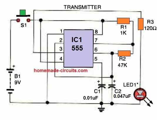
The transmitter circuit shown above produces IR light pulses through LED1, with a 320 Hz frequency (set by R2).
This frequency is focused at the phototransistor Q1 of the receiver circuit. This causes the phototransistor's collector to oscillate at the same 320 Hz frequency.
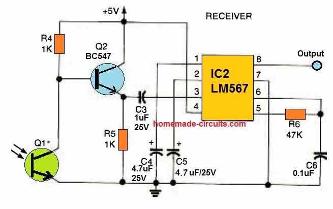
This frequency is boosted by the BC547 transistor and applied to the input pin#3 of the IC LM567.
The LM567 detects the 320 Hz signal as soon as it reaches the phototransistor, which instantly causes the output pin#8 of LM567 to turn low.
If the pulses of some other frequency is focused to the phototransistor, the LM567's output stays high and unresponsive, because it is calibrated to respond only for 320 Hz (as set by R6).
If you wish to operate the remote control with some other frequency, make sure to use identical values for R2 and R6, so that the transmitter frequency matches the receiver's detection frequency.
Remember that the LM567 operates between 100 Hz and 1 kHz and the detection frequency range must not be selected beyond these limits.
A multi-channel remote control system may also be created by substituting R2 with additional number of resistors (for multiple frequencies) and LM567s set to the desired frequencies.
Switching an Output Load
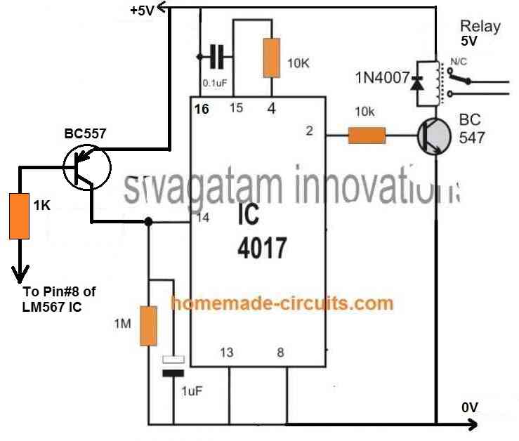
If you want to switch an output load ON/OFF at pin#8 of the LM567, you can do it by integrating a 4017 IC flip flop circuit with pin#8 of LM567.
To implement this you just have to integrate the following 4017 flip flop relay circuit with pin#8 of the LM567 circuit explained above.
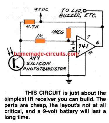
Simple Infrared Receiver using IC 741
Infrared Remote Control Circuit using IC 555 and Transistors
Here's a straightforward infrared switch designed for remote control purposes. It utilizes a typical IR LED and IR diode detector pair, specifically the CGIY89A/BPW50 components.
Transmitter Circuit
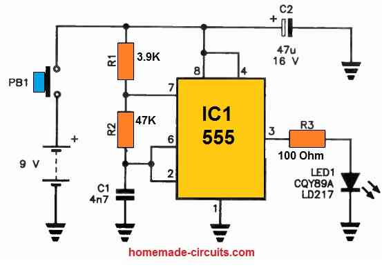
The 555 IC based IR transmitter circuit generates a series of pulses to drive the IR LED.
IR Receiver
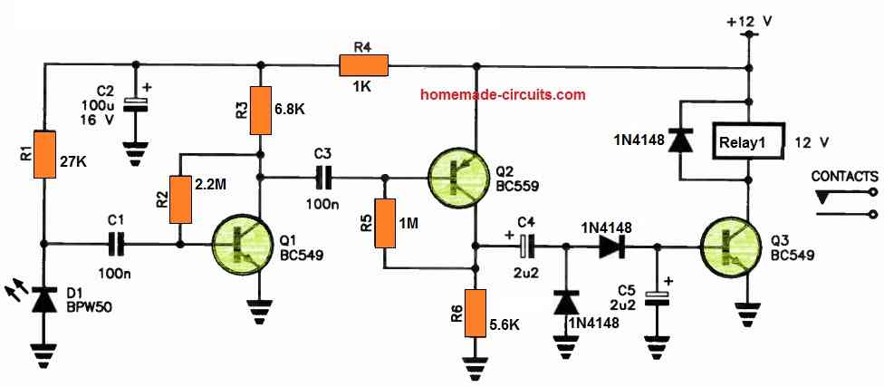
These pulses are then picked up by the IR receiver circuit through the BPW50 IR sensor and subsequently amplified by a high-gain amplifier, employing Q1 and Q2.
The output from Q2 undergoes rectification via a voltage-doubler rectifier, which supplies the base current required for the relay driver, Q3, ultimately enabling relay operation.
The transmitter is enclosed within a compact handheld enclosure, powered by a 9 V transistor radio battery.
In contrast, the receiver is powered by a 12 V DC source, such as a plug-in adapter. It's worth noting that all the components used in this setup are readily available at electronics retailers.



Discussion & Solutions
how many mAh need for this circuit ?
100mA
you can try the second circuit from this link:
https://www.homemade-circuits.com/2013/03/simple-reliable-infrared-ir-remote.html
Hello Sir, we have to make this IR remote control for receiving part in our final year project. Our fyp is "Room automation system for disabled persons" in which we have to control electronic equipments like light, fan,AC and non electronic equipments like door, curtain etc…. we have to open/close these mentioned equipments…. so can this remote control circuit given by you can be useful in our project??? please guide me and if any modifications needed, do tell about them. and can u give the code that is burnt in the controller ic in above circuit? waiting for your prompt reply anxiously… thanks. 🙂
Hello Maria,
Te above circuit is not so reliable. I'll recommend using LM567 IR remote circuit as shown below:
https://www.homemade-circuits.com/2013/03/simple-reliable-infrared-ir-remote.html
Thank you so much Sir for your prompt reply 🙂 Sir,actually controlling light/fan/ac is somewhat easy but closing/opening doors, windows and curtains is not so easy, it will require motors and some complications will be involved for achieving this furthermore we have to include temperature/humidity and light sensors also. So i am confused how will I achieve all of this. Please guide me how should I start up. I have to implement my project using Micro Pro C, MP lab, Proteus. And our project involves 3 main parts: 1)Communicate IR sensors with micro controllers. 2)Communicate wirelessly micro controllers with other micro controllers. 3)Communicate wirelessly motors with micro controllers.
Hopefully waiting for your help Sir.
You are welcome, I wish I could help you with all those stages, however the mentioned stages appear quite complex and are not within my easy reach, so I am sorry I won't be able to go beyond the IR remote control stage explanation.
ok Sir no problem if it's beyond your reach… then sir give me a detail explanation of IR remote control working so that I can explain it in my presentation…the questions that may be asked from this topic, brief me about them in document type link. thanks
I have already explained it elaborately in the above article, if you have specific questions you may ask them, I'll try to clarify them.
SIR PLZ GIVE ME A EASY FLASHING CIRCUIT VERY EASY PLZ
try this one:
https://www.homemade-circuits.com/2011/12/how-to-make-single-transistor-led.html
SIR PLZ GIVE ME A CIRCUIT WICH CAN FLASH 12 VOLT LAMP PLZ SIR
try this one:
https://www.homemade-circuits.com/2011/12/build-simple-how-to-build-universal.html
i'll try to find it
sir,plz give us a simple mini project of optical communication .. i am waiting for ur rply.. thanks…
Hi Maria, pls provide full details of your project requirement, I will try to help.
I am sorry, I don't have much idea about the concept.
don't have much idea about PICs, sorry….
i have made this circuit. everything is well i tested, but tsop. the output still high even i press remote to it…. everytime i power it on. the relay active (connected to pin 2 of 4017). what wronge sir…please help..!
connect a 10k resistor between pin4 and pin15 and connect a 0.22uf or any close value cap across pin15 and positive…see if it helps.
i found the problem sir..when i test the circuit without tsop1738. it works well. so, i try to replace tsop1738 with tsop1138. it works well even under day light or cfl lamp. i use it to control the 220v 1500w chickent washing machine and work with only a cheap cell phone charger as power supply..it is very useful sir…thank much.
OK great, thanks!
yes, but there shouldn't be any obstacle in between….
sir plz sort out my project …………..
hi sir…i am girish. i didn't get the phototransistor TSOP 1738, but in my area TSOP1838 is available .can i use that here…but i didn't get the pin configuration on internet…so can you help me???
Hi GR, you can use it in the above circuit,
pin2 is ground, pin1 is output and pin3 is Vs(supply)
the image is shown, hopefully it's correct:
hai sir i want to control many load pls help me sir
with the above simple design only one load can be controlled.
sir i need a relay range
HI swagatam ….
please help me .. is that a 12v relay or a 5v relay..
Anuj, it's a 12v relay
Sir, can you please suggest a circuit for the below mentioned purpose.
"Current must flow in one direction and the amount must be controlled by a regulator (like in ceiling fans). And on moving the regulator in another direction the current must flow in another direction."
Sorry Stavan, the given data is not sufficient, pls provide more precise information
Hi Swagatam,
As Parthi Ban quoted the requirement of many loads, is it possible to use uC for the same? But for that we need to diagnose which button on Remote was pressed, can we detect that? (using the circuit you provided or any other).
What's the difference between IR and RF wireless communications? (w.r.t. the current purpose).
I definitely want to use uC, please suggest which one should i choose. say for controlling a minimum of 6 loads.
Can you help in uC also?
Anyways great job Dude !!
Hi Rahul,
Thanks!
A uC may not be needed for controlling more loads, it can be done by using separate receivers for each load and with a transmitter handset having individual buttons, just as we have in TV remotes.
I would be addressing one such design soon in my blog.
IR is Infrared and Rf is Radio frequency, IR cannot pass through walls, Rf can.
Sir ,
can i have circuit diagram for 'REMOTE CONTROLLED SWITCH BOARD' . through this i can operate 2 lights , 1 fan, 1 AC, 1 TV.
hi Swagatam ,
i want to make "remote controlled switch board" through which i can operate 4-5 appliances bye remote control. so please suggest me circuit diagram with detail.
Hi Abhishek,
You will see this circuit soon in my blog….keep in touch
thank u sir,
i wil follow ur posts.
Sir, in the design you have used a relay.What kind of relay is it?And what is the source of supply?
It's 12V, 400 ohms, SPDT, you can see it in the image below. the square orange colored block is the relay
Sir, in the remote control circuit the feed is only 230Vac.What will be the relay rating?In this circuit there is no need of any external DC supply.Please help.
Partha, the power supply is clearly shown at the top section of the circuit using a transformer, bridge network….the green color box is the relay coil.
Sir ,this means the relay will work in 12V dc which will be fed from step down transformer and the bridge.Please help me to understand .Thanks.
yes that's correct
Sir, one more doubt about the value of R4 .Is it 4K7?
yes it's 4k7 = 4.7k
Hii sir is there any possibilities of using a transformerless circuit for this circuits power supply? I know its critical but I want to makes rhings more compact in a box thank you. 😀
Hi Srishan, you can try the one that's shown in the following article:
https://www.homemade-circuits.com/2011/12/cheap-yet-useful-transformerless-power.html
put two zeners in parallel if possible for better safety.
use 15V/1watt zeners