• Skip to main content
  • Skip to primary sidebar

Homemade Circuit Projects

Need circuit help? Post them in the comments! I've answered over 50,000!

Blog | Categories | About | Contact | Calculators-online
You are here: Home / Power Supply Circuits / Transformerless Power Supply Circuit using MJE13005

DIY Circuits | Learn Basics | Arduino Coding


Transformerless Power Supply Circuit using MJE13005

Last Updated on July 7, 2023 by Swagatam 78 Comments

The following article presents a very simple low current 220 V mains operated transformerless power supply circuit using an inexpensive MJE13005 transistor and few other passive electronic components.

As can be witnessed in the given circuit diagram, the design is extremely straightforward.

How it Works

Transistor T1, which is a high voltage NPN transistor MJE13005 forms the main active component in the circuit.

Rest of the components are positioned just for supporting the conduction of T1 and for the required stabilization.

The circuit can be understood with the following points:

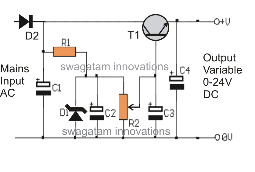
Mains input is fed across D2 and the negative line of the circuit.

D2 rectifies the mains AC, while C1 filters to some reasonable levels.

R1 drops the current to tolerable limits in order to provide the required base bias for T1.

C2 provides further filtration to the voltage generated after R1.

D1 clamps the base voltage at the base of T1 to 24V, such that the maximum output voltage can never exceed this limit.

A mirror voltage which is always equal to the zener value is generated at the output, however the presence of R2 enables the response to become variable.

The adjustments made through R2 effectively varies the zener voltage right from zero to the maximum value, that is up to 24V.

Thus the obtained output becomes variable from zero to 24V.

However since the voltage is acquired across the emitter/ ground of the transistor, the current gets restricted to very modest levels, at 25mA to be precise.

The zener voltage though may be increased to any desired limits.

WARNING: THE WHOLE CIRCUIT IS NOT ISOLATED FROM MAINS AC, THEREFORE IS EXTREMELY DANGEROUS TO TOUCH WHILE IT'S UNCOVERED, AND POWERED CONDITION. MAKE SURE YOU HAVE MAINTAINED ALL THE NECESSARY PRECAUTIONS WHILE HANDLING THIS CIRCUIT.

MJE13005 based transformerless power supply circuit

Parts List

R1 = 100k
R2 = 10K POT
C1 = 4.7uF/300V
C2 = 10uF/100v
C3,C4 = 100uF/30V
D1 = 24V, 1WATT, ZENER DIODE
D2 = 1N4007
T1 = MJE13005

You'll also like:

  • buck converter CM DM modesSimple Buck Converter Circuits using Transistors
  • rfdischargegeneratorcircuitMaking a Strong RF Discharge Circuit
  • half wave doublerSimple Voltage Multiplier Circuits Explored
  • 9 volts dc battery eliminator circiut 002Making a Regulated 9V Battery Eliminator Circuit

Filed Under: Power Supply Circuits Tagged With: MJE13005, Power, Supply, Transformerless

About Swagatam

I am an electronics engineer and doing practical hands-on work from more than 15 years now. Building real circuits, testing them and also making PCB layouts by myself. I really love doing all these things like inventing something new, designing electronics and also helping other people like hobby guys who want to make their own cool circuits at home.

And that is the main reason why I started this website homemade-circuits.com, to share different types of circuit ideas..

If you are having any kind of doubt or question related to circuits then just write down your question in the comment box below, I am like always checking, so I guarantee I will reply you for sure!

Previous Post: « Infrared (IR) Motor Remote Control Circuit
Next Post: High Voltage Transistor MJE13005 – Datasheet, Application Notes »

Reader Interactions

Comments

rich13 says:
May 30, 2016 at 12:54 am

Hello,
I'm sure you know this is very late asking a question regarding your design. Hopefully you will read this.
I see your parts list, but can you give values for the wattage for…. R1. Will this need adjustment in case of modifying the output, I've, if output is required at 12v, will RI wattage be different?

Many thanks

Rich

Reply
Swagatam says:
May 30, 2016 at 3:22 pm

Hello, R1 is 1/4 watt rated..it's not recommended to adjust its value because lowering it can damage the transistor.

Reply
frencho says:
November 13, 2015 at 8:32 am

Hello,
One question regarding your schematic : would it work with only the phase 220VAC line and no neutral.
I'm working on a power supply for a small radio module to controle light switch. behind the light switch I don't have the neutral line.

Reply
Swagatam says:
November 14, 2015 at 6:47 am

hello, you can use an "earthing" line as the neutral, for example it could be your bathroom water tap line…

Reply
Swagatam says:
October 13, 2015 at 4:17 am

It's D1, I'll correct it in the article soon

Reply
Andreas Christodoulou says:
October 12, 2015 at 5:45 pm

Which diode is wrong???
Is it the 24V zener or the general purpose 1N4007 ???

Reply
Swagatam says:
May 18, 2015 at 11:58 am

try a 400V capacitor for C1, or simply don't use anything, eliminate C1 and first try the circuit without it.

Reply
Swagatam says:
April 26, 2015 at 6:01 am

please translate in english

Reply
Manoj kumar says:
December 30, 2014 at 8:01 pm

Bro can I use this pcb with smd led? If yes then how much number of minimum qnd maximum led I cn use..,

Reply
Swagatam says:
December 31, 2014 at 7:41 am

Bro I won't recommended this circuit for SMD because SMDs are costly and we require foolproof design, so better go for a 12V SMPS adapter available readymade.

Reply
Vikram Sha says:
July 3, 2014 at 5:57 am

hi sir im a electronic hobbiest
can i use this circuit to power 100 led lights

Reply
Swagatam says:
July 3, 2014 at 12:02 pm

Hi Vikram, use the following circuit, the above will not work:

https://www.homemade-circuits.com/2012/03/how-to-make-simplest-1-watt-led-driver.html

put all the LEDs in series and join it with the output of this circuit

Reply
Bharani Daran says:
March 15, 2014 at 12:48 am

Dear Sir,

Do you have any circuits high current application above my spec

Thanks & Regards

S.Bharanidaran

Reply
Swagatam says:
March 15, 2014 at 8:21 am

Dear Bharani,

According to me an SMPS would be the correct option choice for driving a high watt LED.

you can easily procure a readymade 24/1amp smps unit ad power your LED through

it….smps amp is not crucial as long as the voltage does not exceed above the led specs.

Reply
Bharani Daran says:
March 13, 2014 at 1:57 pm

Dear Sir,

The above circuit use in 23v/300ma Led light(7watts)

Thanks & Regards

S.Bharanidaran

Reply
Swagatam says:
March 14, 2014 at 3:27 pm

Dear Bharani,
No, it's not suitable for high current applications.

Reply
Swagatam says:
December 17, 2013 at 6:41 am

T1 is the main component which does the required voltage dropping.

Reply
Avik Paul says:
December 8, 2013 at 11:33 am

sir,
Do you have any circuit which provide 12v 100ma current…..

Reply
Swagatam says:
December 9, 2013 at 5:26 am

Avik, you can use the above circuit and add an overboard transistor across the existing mje13005 for boosting current to the required levels.
I'll try to update it soon here.

Reply
cheenu ditya says:
October 29, 2013 at 12:47 pm

What if i inverse the polarity of capacitors in this ckt ? They will explode right sir??

Reply
joshua richard says:
October 1, 2013 at 11:07 am

about 500-1A cause i will use it to drive a TDA 2822M and charge two smartphones

Reply
Swagatam says:
October 2, 2013 at 4:35 am

For charging batteries you will have to employ an smps circuit, other forms won't be safe as these may not be isolated from mains AC and also not capable of producing higher current outputs.

Reply
joshua richard says:
September 30, 2013 at 11:03 am

hi
can you help me 5v-12v transformer-less power supply circuit

Reply
Swagatam says:
September 30, 2013 at 3:02 pm

hi, what's your current requirement? please specify the current requirement.

Reply
Swagatam says:
September 23, 2013 at 2:13 pm

sorry 1 amp won't be possible.

Reply
Swagatam says:
July 24, 2013 at 3:42 pm

Dear Aruna,

According to me there's no possibility of a surge in this circuit.

Reply
SHIV-FOUNTAIN says:
July 20, 2013 at 3:54 pm

can you please upload high power led driver circuit for 400w led.

Reply
Swagatam says:
July 22, 2013 at 4:06 am

you can use the following circuit:

https://www.homemade-circuits.com/2011/12/make-hundred-watt-led-floodlight.html

just replace the components by calculating them with the given formula.

You will need an external smps to drive the above circuit

Reply
Back to Newest

Need Help? Please Leave a Comment! We value your input—Kindly keep it relevant to the above topic! Cancel reply

Your email address will not be published. Required fields are marked *

Primary Sidebar

circuit simulator image


Subscribe to get New Circuits in your Email


Categories

  • Arduino Projects (93)
  • Audio and Amplifier Projects (133)
  • Automation Projects (17)
  • Automobile Electronics (101)
  • Battery Charger Circuits (85)
  • Datasheets and Components (109)
  • Electronics Theory (149)
  • Energy from Magnets (27)
  • Games and Sports Projects (11)
  • Grid and 3-Phase (20)
  • Health related Projects (27)
  • Home Electrical Circuits (13)
  • Indicator Circuits (16)
  • Inverter Circuits (95)
  • Lamps and Lights (159)
  • Meters and Testers (71)
  • Mini Projects (28)
  • Motor Controller (68)
  • Oscillator Circuits (28)
  • Pets and Pests (15)
  • Power Supply Circuits (91)
  • Remote Control Circuits (50)
  • Renewable Energy (12)
  • Security and Alarm (64)
  • Sensors and Detectors (106)
  • SMPS and Converters (34)
  • Solar Controller Circuits (60)
  • Temperature Controllers (43)
  • Timer and Delay Relay (49)
  • Voltage Control and Protection (42)
  • Water Controller (36)
  • Wireless Circuits (30)


Other Links

  • Privacy Policy
  • Cookie Policy
  • Disclaimer
  • Copyright
  • Videos
  • Sitemap


People also Search

555 Circuits | 741 Circuits | LM324 Circuits | LM338 Circuits | 4017 Circuits | Ultrasonic Projects | SMPS Projects | Christmas Projects | MOSFETs | Radio Circuits | Laser Circuits | PIR Projects |

Social Profiles

  • Twitter
  • YouTube
  • Instagram
  • Pinterest
  • My Facebook-Page
  • Stack Exchange
  • Linkedin


Recent Comments

  • Swagatam on Arduino 2-Step Programmable Timer Circuit
  • Swagatam on Simple Buck-Boost Converter Circuits Explained
  • Swagatam on IC IR2111 H-Bridge MOSFET, IGBT Driver IC: Full Datasheet, Circuit Diagram
  • Swagatam on Electronic Circuit Projects, Tutorials, and Practical Engineering Solutions
  • Kadir on Simple 3 Phase Inverter Circuit

© 2026 · Swagatam Innovations