In this article we will comprehensively study a transistor relay driver circuit and learn how to design its configuration by calculating the parameters through formulas.
Importance of Relay
Relays are one of the most important components in electronic circuits. Especially in circuits where high power transfer or mains AC load switching is involved, relays play the major role in implementing the operations.
Here I have explained how to correctly operate a relay using a transistor and apply the design in electronic system for switching a connected load without issues.
For an in-depth study regarding how a relay works please read this article
A relay, as we all know is an electromechanical device which is used in the form of a switch.
It is responsible for switching an external load connected to its contacts in response to a relatively smaller electrical power applied across an associated coil.
Basically the coil is wound over an iron core, when a small DC is applied to the coil, it energizes and behaves like an electromagnet.
A spring loaded contact mechanism placed at a close proximity to the coil immediately responds and gets attracted toward the energized coil electromagnet force. In the course the contact connects one of its pair together and disconnects an complementary pair associated with it.
The reverse happens when the DC is switched OFF to the coil and the contacts return to its original position, connecting the previous set of complementary contacts and the cycle may be repeated as many times as possible.
An electronic circuit will normally need a relay driver using a transistor circuit stage in order to converter it’s low power DC switching output into a high power mains AC switching output.
However the low level signals from an electronic which may be derived from an IC stage or a low current transistor stage may be be pretty incapable of driving a relay directly. Because, a relay requires relatively higher currents which may be normally not available from an IC source or a low current transistor stage.
In order to overcome the above issue, a relay control stage becomes imperative for all electronic circuits which need this service.
A relay driver is nothing but an additional transistor stage attached with the relay which needs to be operated. The transistor is typically and solely employed for operating the relay in response to the commands received from the preceding control stage.
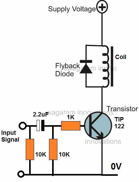
Circuit Diagram
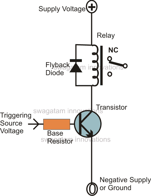
Referring to the above circuit diagram we see that the configuration only involves a transistor, a base resistor and the relay with a flyback diode.
However there are a few complexities that need to be settled before the design could be used for the required functions:
Since the base drive voltage to transistor is the major source for controlling the relay operations, it needs to be perfectly calculated for optimal results.
The base resistor value id directly proportional to the current across the collector/emitter leads of the transistor or in other words, the relay coil current, which is the collector load of the transistor, becomes one of the main factors, and directly influences the value of the base resistor of the transistor.
Calculation Formula
The basic formula for calculating the base resistor of the transistor is given by the expression:
R = (Us - 0.6)hFE / Relay Coil Current,
- Where R = base resistor of the transistor,
- Us = Source or the trigger voltage to the base resistor,
- hFE = Forward current gain of the transistor,
The last expression which is the “relay current” may be found out by solving the following Ohm’s law:
I = Us/R, where I is the required relay current, Us is the supply voltage to the relay.
Practical Application
The relay coil resistance can be easily identified by using a multimeter.
Us will also be a known parameter.
Suppose the supply Us is = 12 V, the coil resistance is 400 Ohms, then
Relay current I = 12/400 = 0.03 or 30 mA.
Also the Hfe of any standard low signal transistor may be assumed to be around 150.
Applying the above values in the actual equation we get,
R = (Ub - 0.6) × Hfe ÷ Relay Current
R = (12 – 0.6)150/0.03
= 57,000 Ohms or 57 K, the closest value being 56 K.
The diode connected across the relay coil though is no way related with the above calculation, it still cannot be ignored.
The diode makes sure that the reverse EMF generated from the relay coil is shorted through it, and not dumped into the transistor. Without this diode, the back EMF would try to find a path through the collector emitter of the transistor and in the course damage the transistor permanently, within seconds.
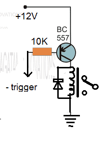
Relay driver Circuit using PNP BJT
A transistor works best as a switch when it is connected with a common emitter configuration, meaning the emitter of the BJT must be always connected directly with "ground" line. Here the "ground" refers to the negative line for an NPN and the positive line for a PNP BJT.
If an NPN is used in the circuit, the load must be connected with the collector, which will allow it to be switched ON/OFF by switching its negative line ON/OFF. This is already explained in the above discussions.
If you wish to switch the positive line ON/OFF, in that case you will have to use a PNP BJT for driving the relay. Here the relay may be connected across the negative line of the supply and the collector of the PNP. Please see the figure below for the exact configuration.
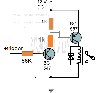
However a PNP will need a negative trigger at its base for the triggering, so in case you wish to implement the system with a positive trigger then you may have to use a combination of both NPN and PNP BJTs as shown in the following figure:
If you have any specific query regarding the above concept, please feel free to express them through the comments for getting quick replies.
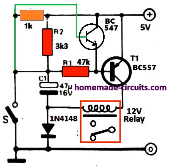
Power Saver Relay Driver
Normally, the supply voltage for a operating a relay is dimensioned to ensure that the relay is pulled-in optimally. However, the required retaining voltage is typically much lower.
This is usually not even half the pull-in voltage. As a result the majority of relays can work without problems even at this reduced voltage, but only when it is ensured that at the initial activation voltage adequately high for the pull-in.
The circuit presented below may be ideal for relays specified to work with 100 mA or lower, and at supply voltage below 25 V. By using this circuit two advantages are assured: first of all the relay functions using substantially low current; at 50 % less than the rated supply voltage, and current reduced to around 1/4 of the actual rating of the relay! Secondly, relays with higher voltage rating could be used with lower supply ranges. (For instance a 9 V relay that is required to operate with 5 V from a TTL supply).
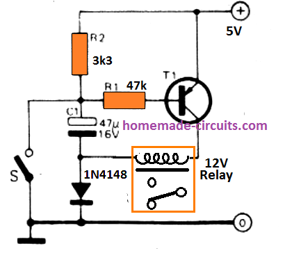
The circuit can be seen wired to a supply voltage capable of holding the relay perfectly. During the time S1 is open, C1 gets charged via R2 upto the supply voltage. R1 is coupled to the + terminal and T1 remains switched OFF. The moment S1 is presed, the T1 base gets connected to supply common through R1, so that it switches ON and drives the relay.
The positive terminal of C1 connects to the common ground through the switch S1. Considering that this capacitor initially had been charged to the supply voltage its -terminal at this point becomes negative. The voltage across the relay coil therefore reaches two times more than the supply voltage, and this pull in the relay. Switch S1 could be, certainly, be substituted with a any general purpose transistor which can be switched on or off as required.


Comments (131)
Your help is appreciated. I have a 2 x AA battery powered wireless microphone transmitter that I want to also and primarily power from a 5V wall adapter with a relay to swap over to the batteries if I lose wall power. The idea is to not rely on the batteries, because of they go dead, I lose the channel and have to re-sync with the remote receiver, hundreds of feet away, and I’ve lost my music transmission. The key is to not allow the transmitter to lose power, or it loses its transmission frequency. I have the regulator and all working to get 5V -> 3V, and it works when I go from wall power to battery (I switch off the wall adapter to simulate a power failure), but going the other way, (restoring wall power), there is no 5V for a second or so, while the circuit builds up it’s voltage, but the relay trips and disconnects the battery. (If I had a make before break relay, that would do it) The power to the transmitter drops and it turns off ! How can I delay the relay contact transfer until the wall adapter reaches nearly 5V? Sort of a time delay, but powered by the very thing causing the delay !!!
Hi, I can certainly help you with an easy solution, but before that I want to ask you about the need for the relay here.
If it is for the changeover action, then it is simply not required….we can implement the same using diodes.
Let me know your thoughts on this, then I can give you the finalized diagram.
I’ve been trying to use the schematic in the Power Saver Relay Driver section.However, it causes a 10-25ms glitch at power-on for the circuit (trigger switch is off). When power is first applied, the relay turns on for this short time.
The glitch was visually verified by having the relay control an LED.
From that point on, the circuit acts as described at 7-15V (but not at 5V).
I ran a Tina-Ti transient simulation (attached), and sure enough, there is a glitch upon applying power. Having the relay turn on with out the input switch trigger is unacceptable for my application.
Do you have a solution for this problem?
Thanks!
Thank you for your interesting analysis.
Please try the following modification and let me know if it works or not:
Respected Brother,
what is the minimum trigger voltage at the Base of BC547 to switch a 12v T73 type relay?
Regards
Nisar
Hi Nisar,
the minimum trigger voltage at the Base of BC547 for any type of load will be around 0.6V….
Thank you very much for your prompt reply.
God bless you.
Regards
It’s my pleasure!
Hello Sir, please Sir I was to repair an four plate induction cooker.The power supply uses a relay which switches on the Neutral connection to a diode ic ac terminal pin.The other pin of the diode ic gets direct contact to the Live of the mains.
However,the relay is not switching,and after careful examination,I saw two transistors 3F(BC857)and 4F(BC860) .Both transistors are wired in series with their collector pins connected to the relay coils independently. I measured the supply voltage to the base of the transistors to the emitter and measured 14Volts.However,the collector voltages measured very less about 6volts.
I thought to replace the two transistors 3F and 4F but they are not common within my locality or nearby Electronics stores.Please Sir, I needed a schematics comprising of similar but employing the use of simple transistors to switch on the relay.
Hello Lawal,
You can use any ordinary BJT for driving a relay. The only thing that matters is the current and the voltage rating of the transistor which must be correctly rated to handle the relay coil current. I have explained the formula in the above article, you can use it to determine the suitable transistor for your relay. For this you will have to first find out the coil resistance of the relay.
Regarding the series configuration, are the transistors configured in the following manner?
Please Sir, the two transistors were not configured in that manner,after I checked several times using continuity test,I found out that,the transistor labelled 3F(PNP),has a 47k smd resistor connected across it’s base and the emitter.
The emitter is connected to a voltage supply of 14.2 voltage output from the ferrite core transformer transformer.
The base is connected further to R23 which is more of a shiny dot conductor on the motherboard .
The emitter is further extended through connection to C64 which also look like a shiny points on the motherboard possibly smd capacitor.
The collector of this transistor is connected to one of the relay coils terminal.
2.The second transistor 1F (NPN), also has 10K resistor connected across it’s base and emitter.The emitter is connected to the ground of the voltage supply 14.2V output from the ferrite core transformer.So in this case, when I measured the voltage across the two emitters, (PNP and NPN), I recorded 14.2V.
The base of the 1F transistor is further connected to 2.2K smd resistor and the other terminal connected further to the third pin of a microcontroller R5F2127.
The collector of 1F is connected to one of the other relay coils terminal.
The induction cooker has four burners , and it has two separate identical Motherboard each with two coils from heating.
The whole section is operated digitally.
Hi Lawal,
I think it is better to remove the transistors from the board and then check it with a meter. Without seeing the schematic it can be difficult to understand the layout of the transistor configuration.
Hi Swagatam good circuits I am trying to make a H bridge driver for a12v rf latching relay to be tiggered to open one way then the other way any hints would be appreciated Bryan
Thanks Bryan, I don’t think an H bridge would be required for this, it could be easily implemented using an IC 555 set/reset circuit.
Hi swagatham ji namaskar your simple Quadcopter circuit and how to design simple Quadcopter using aluminium extrusion pipes has been my Bhagavad Geetha i almost read it daily for the wonderful explanation with pics is really great great for hobbyist like me thank you ji
Raghu k
DSP tamilnadu police service
9344477986
Thank you Raghu Rao, I am glad you liked the post on quadcopter. I appreciate your kind words very much. All the best to you.
Нello you have a very good post about relay management
my question to you is:
I am doing a project to control coils of pneumatic distributors which need to be controlled is energy saving.
The parameters are as follows 3.5 A ; 24 volts;
The idea is that the distributor plunger will move at 24 volts for 4.5 m/s. then I need a holding voltage of 4 to 7 volts (5 volts) or 1/4 of nominal.
I figured out how your relay circuit works. it is suitable for the coil also.
How should I connect the coil and how will I get a trip time of about 5 m/s. and there should be immediate on/off without time hold ( real time control).
Проблема ми е бързодействието.
Thank you for reading and liking this post.
Any type of solenoid coil with proper ohm rating can be used with a transistor diver just like a relay, it will work.
To get a brief switch ON time of 5 ms you can add a capacitor in series with the base resistor as depicted in the following diagram:
You can adjust the value of the capacitor to get the precise 5 ms trip time on the coil
Many thanks I will create the scheme and return a reply.
what transistor do you recommend to use because of 24 volts and what resistors.
thanks for your assistance
No problem!
You can try TIP122 transistor, and try the resistor as given in the diagram. The capacitor value can be changed to suit the delay requirement.
Please delete my comment below, I connected relay side to emitterin stead of collector. So your explanation is correct.
This means we have to READ an understand completely, before proceeding.This means also your explanation wil be saved to my favourites!
Thanks!!
No problem Johan, I understand! I have deleted your previous comment!
I like your site.
I really liked the old 2N2222A and the 2N2907 TO-18s, that should date me as an
EE retired as of 2017. The IMMC ( Integrated Mission Management Computers ) flying in the Global Hawk UAVs are my Babies The PCB designs were complex at 2.5GHZ PCIe gen_2 speeds ! magic
The PV MOSFET drivers (IXYS FDA217 AND SIMILAR) can provide output isolation for low speed , high power AC/DC applications.
Also reed relays are great for many applications.
Thank you for your valuable feedback, much appreciated!
Always check that all parts, active and passive are not dissipating more than they are rated. Your finger
will be OK at 100milli watts more or less. If you have to get your finger off, it is too hot to be reliable.
It is Tym Sir, I forgot for a photo proof, here it is; https://ibb.co/0KMNMzd
Hi Tym, sorry, that link is not opening, if possible please try some other image hosting site.
Here is another link I tested and OK;

but the first link works for me, I tested clicking it in the above comment, just a feedback Sir.
Yes it is working now….and the connections look OK to me.
Hi Sir, I tried power saver driver circuit. I used an SS8550, and an ON/OFF switch for S1, and a 2.7K (from my storage) for R2 instead of 3.3K and I think it is not a problem, and the rest are the same as in above picture. But it did not work with 5V. I tried changing R1 to 15K picked from my storage but the relay still doesn’t pull in.
I used adjustable voltage power supply and noted that the relay starts to make clicking sounds at around 5.4V but doesn’t pull in (yes, I always wait some seconds for capacitor to be charged before turning ON the switch). It starts to pull in at around 6.35V but with a weak click sound, and also has a delay of about 2 seconds between switching OFF and ON. The voltage at the relay coil(400 ohms) is 5.55V under operation.
6.35V supply is about 53% of a 12V relay that is close to your description of 50%. But it does not work with 5V. I think something is wrong with the circuit picture.
Thank you Tym for trying this circuit. Actually this circuit was contributed by another person, it is not my design, so I am not 100% sure about the working of the design.
You can try increasing the C1 value to 100uF and check the response. The circuit is supposed to initiate only when the switch “S” is pressed after applying the 5 V supply.
However even at 6.35V, it is not bad, since normally it would have required at least 10V to activate the relay.
If I use 100uf capacitor, can the capacitor and circuit be harmed by turning the switch on and shorting to ground?
The capacitor is connected to the resistors and the relay coil so it cannot harm anything in the circuit.
What I understand is the charged capacitor(about 6V) is shorted to ground when I turn the switch ON, there is only a 1N4148 between the capacitor minus pin and ground line, I had read somewhere that capacitors should be discharged by proper resistance/resistor, so my question is this instant discharging method safe for capacitor for this amount of voltage?
I hope you understand my writing.
Sorry for my poor broken English Sir.
A capacitor will not get damaged if its terminals are shorted unless you do it too rapidly. It can get damaged instantly only in one condition, if the charging voltage across it exceeds the maximum rating printed on its body. For example if the printed value on the capacitor 25 V then if this voltage is exceeded, then the capacitor might start leaking or might explode..
Moreover, your capacitor is getting the charging voltage through a resistor so the stored current content is less.
Thank you for the lesson and clarification.
Hi Sir, I tried changing capacitor values. First, 100uf, minimum pulled-in voltage is around 5.64V, charging delay time (initial charging time for capacitor before Switch ON) is above 3 seconds. I noticed there is also a delay of about 1 second for relay cut-off after Switch OFF.
Then 220uf (but it is above 190uf according to my DMM capacitance meter), minimum pulled-in voltage is around 5.17V, charging delay time is about 4 seconds, cut off delay time is about 2 seconds.
Finally, 330uf (I couldn’t check it because it is beyond my DMM maximum scale), minimum pulled-in voltage is around 5.01V, charging delay time is about 5 seconds, cut off delay time is above 2 seconds.
So the facts with this circuit are some delay at initial or every time after the Switch is OFF and also has some delay for the relay to be cut off.
Good observations Tym, appreciate it. I hope the readers will find the information useful.
“… transistor works best as a switch when it is connected with a common emitter configuration, meaning the emitter of the BJT must be always connected directly with “ground” line.”
Oversimplification, especially when having high impedance triggering source we need to drive the relay or any low impedance load and common collector is a perfect solution.
Greetings!
I would like to build the last circuit, looks very promising for my project. Tho, i was wondering, i don’t see any diodes parallel to the relay coil. I see another in series to the ground, isn’t that a problem?
Thank you for your kind answer in advance!
Hi, in the last circuit the C1 and the diode probably will not allow the back emf to harm the transistor, it is safe according to me..
Great then, thank you for your kind and quick answer! ^^
Thank you, my pleasure
Hi, I have a relay of 24VDC.-.-.- for coil voltage.And I want to design it’s power without using a TX?From 220v AC.
Hi, You can build a transformerless power supply using a 0.33uF/400V capacitor, a bridge rectifier, and a 1000uF/50V filter capacitor to power the 24V relay.
Sir could you tell me what the use of diode is in the power saver relay driver circuit?
The diode along with the capacitor helps to form a voltage doubler circuit.
Two thoughts. First I see no throw back diode to protect the transistor when switch is opened.
Second is the assumption that running a relay at lower voltage is ok. First a typical 12 volt relay will usually pull in at around 6-7 volts and dropout at 3-4 volts. So using 5 volts does not allow much for variations that occur with wide temperature changes. You should also be aware that
relay contacts current carrying capacity are affected by the force pressing them together which in
this case is being reduced substancially. If switching currents of a milliamp or less and depending on the contact materail you can risk loss of contact over time and environmental changes. Better choice is to use a magnetic latching relay. Your approach would be fine when driving a solenoid.
Thanks for the useful feedback!
Hello sir i tried to simulate the power saver relay driver circuit with the ame parameters but it doesn’t seem to work. The relay doesn’t switch side could you please tell me what could be wrong?
Hello Muzzam, the circuit has only a few parts, so it would be a better idea to build it practically and check how it performs.
And, also can i post the picture of my simulation somewhere so that you could check where i could have made an error
sorry I don’t use simulators, I always believe in building practically and testing
Thank you for your quick response. I am new to electronics. I have few questions if you would answer i would be highly grateful.
1) have you build the power saver relay practically yourself did it work? (I don’t mean to be rude).
2) have u used the same values for the components as shown in diagram.
3) what is the name of the transistor used?
4) what does the (+)on the battery signify and what is that o at the bottom do i have to keep it open?
I have not built it practically, but it was referred from a top reputed electronic magazine, so it will definitely work
ok sir could you tell me the name of that magazine?
Good
Hi,
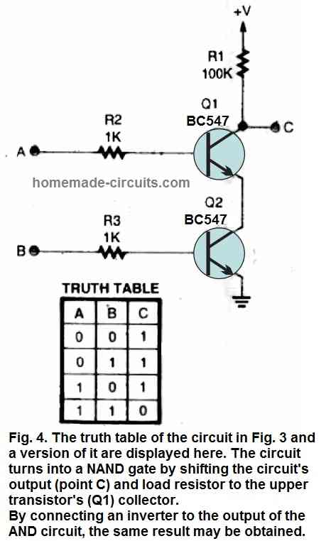
Kindly tell me how you calculated 68K resistance in an example in which you are using both npn and pnp transistors to operate relay.
I did not calculate it, selected it randomly. To calculate it you can use the same formula as use for the relay coil, but in this case the load are two 1k resistors at the collector of NPN. However, you can ignore the upper 1K and consider the current only through the lower 1K, in the formula.
Goodmorning Sir. You say “If you wish to switch the positive line ON/OFF…”, why would I want to use the positive line? Thanks
If you have a PNP transistor and want to make a relay driver with it….then…
Obvious. Sorry. Thanks
No problem!
In the transistor driver description at https://www.homemade-circuits.com/how-to-make-relay-driver-stage-in/
I am unclear how you derived the 10K ohm base resistor in the basic PNP relay driver circuit with a 12v supply and a negative trigger. Can you elaborate a little on that formula?
Thanks
Using the formula will identically give you the 56k value for the PNP driver as well, for a 400 ohm relay, however, from my practical experience I have seen that a 10k usually works good without any dissipation on the BJT, along with a powerful drive for the relay contacts.
Ok, I was wanting to adapt this to drive a solenoid valve with a 24v supply and using a switched ground trigger, and the 10K in the example was confusing me… Thanks for the quick answer:)
You are welcome!
Suppose I have a 12v Relay 400 ohms
BC547
Triggering Voltage=5v (from arduino uno)
How do I determine the hfe?
Thanks for the feedback.
hFE can be determined from the datasheet of the transistor
I mean its min is 110 and max is 800…which do I choose?
you can take any intermediate value, 300 to 500
Hi Swagatam, I have a query please. I am planning to use 433MHz Tx Rx pair ( single channel) to energise a 12v relay, which will require a relay driver as in your example above. For the simple BC557 circuit I have calculated the theoretical resistor value as 41K so I would expect to use 47K. However the Rx will generate a High output which will require the 2 stage example using a BC557 & BC547 and I’m confused about how to calculate the 3 resistor values, can you help please?
Hi Philip, the resistor values for a low DC circuit is never critical, as the transistor have a wide tolerance range for DCs. If the formula gives 41k resistor, then you must use a lower value resistor for the relay driver transistors base, may be a 33 K will be fine.
This 33 K will now become the collector resistance for the BC557, so you can apply the same formula and principle for calculating the BC557 base resistor…..however, again this is not critical and you can simply assign another 33K resistor for the BC557 base also.
Thanks very much for your swift response and advice. I’m just waiting for components to be delivered and I’ll give it a try.
No problem!
hi:
Thanks for sharing. Your posts have been very useful so far. But now I have this need: I have a shunt wich delivers between 50 to 200mV and I need to switch on a relay (12v) as soon voltage appears in the shunt and shut it off about 15/20 secs after it senses no voltage. I was thinking in using a 741 but I understand that a couple of transistors could do the job.
Is there some circuit that I can reasemble to make the task?
Thanks for your help.
Ed.
I am glad my posts are helping you!
You can try the NPN version of the current limiter from the following post
https://www.homemade-circuits.com/simple-current-sensor-circuit-modules/
You can connect a relay with the collector of the transistor along with a free wheeling diode.
However a due to lower gain of the transistor 0.2V may not be sufficient to trigger the transistor. Therefore to increase the gain of the transistor please upgrade the BC547 into a Darlington transistor by adding another BC547 to it.
Thanks for your help..
Hi Swagatam,
I have a different configuration circuit that needs resistor calculations for the relay.
I have no knowledge of electronics.
Please can I talk to you via email?
I can send you the diagram through it.
Kind regards
Hi Swagatam
https://pdfhost.io/v/5VjsoTEBm_AV_soft_startpdf.pdf
The above, how to calculate the relay driver resistor please?
Thank you
Which resistor to change?
R5 or R6 ?
Hi Swagatam,
Please see link https://ibb.co/jw3CnCx
Excuse me for troubling you. I have decided to use this circuit for my final project
since it is for audio purpose. What I need is also an immediate turn off relay once power off.
I have tried to implement your calculation for the value of R1 and R2.
But I cannot get it. Am using DC 28V after rectification.
Please can you help me show how to calculate it? I just need to understand how they
get resistor values for 40Vdc and so on.
Thank you so much
Hi Raj, the supply voltage should be ideally identical to the relay coil voltage rating otherwise the relay may dossipate the extra volatgae through slight heating. Since the base of Q4 is clamped with a 12V zener, the R1 can be calculated in the following manner
R1 = (12 – 0.7) x 200 / relay coil current
Although R2 is not critical, it can be calculated using Ohm’s law
R2 = (28 – 24) / Relay coil current
Hi Swagatam
The coil is 24/650 = 0.037A
For R1 ,
(12-0.7)200 /0.037 = 61k
But at the table is 2k7 for 22vdc. Please can you correct me?
For R2, example
40-24/0.037 = 432R
In the table is stated 470R. Ok it is nearest figure.
Hi Raj, as I have mentioned somewhere in the article, the value of the resistor is not critical. Lower resistor will cause the relay to hold more strongly, and higher resistor will cause lower force. However 2.7K is very low and is incorrect value. This may cause the transistor and R2 to dissipate some heat and waste power.
The calculated value is the accurate value but will require the input supply to be not less than 24V and relay resistance not higher than 650 ohms
A 10K will be quite fine, and will allow the relay work strongly even if the input supply is lower than 24V, or the coil resistance is higher than 700 ohms, and also keep the transistor and R2 cool
Don’t change R6, R5, let them be as they are.
Instead connect another resistor in series with the transistor base. The value can be calculated using the same formula as explained above.
For Ub or the supply use 6V, if the input is 9V.
This 6V is created by the R5/R6 network at the base of the transistor.
Hi Raj, for this diagram the formula is the same as explained in the above article.
Hi Raj,
you can upload it to any free image hosting side such as this https://imgbb.com/ and provide the link through comments, I’ll try to solve it for you.
Hi Swagatam
https://ibb.co/C040fFG
The above, how is the step formula to calculate the relay driver resistor?
And how can I incorporate delay on switching?
Hi Swagatam,
How do I place a capacitor to have a delay on?
Thank you Swagatam,
I will try that
You can put a capacitor in series with a 1N4148 diode between base and ground of VT1. Diode cathode will go to base, anode to capacitor positive, capacitor negative to ground. Also put a 100K in parallel with the capacitor leads. The value of the capacitor will depend on the delay required.
Hi Raj, no need of calculating the relay coil for this design, since the supply is a low current…so the relay circuit needs no change.
Hello sir,thanks for the project. I have a similar one which needs your help. l want to design an incubator circuit using an BC547 npn transistor,an NTC thermistor and a relay. My problem is on how to get the values of resistors to bias my transistor and to control temperature at 37°C. Please help,with calculations involved.
Hello Given, please tell me how the transistor, NTC and the relay are configured? And also tell regarding the NTC value.
the transistor is configured in common emitter configuration and is biased using a voltage divider which comprises of an NTC thermistor and a variable resistor.There is also a base resistor.On the collector is connected a relay and a flywheel diode.Vcc=12VDc. l want to control temperature at 37°C,at which temperature my NTC thermistor resistance will be close to 6K.please help with the calculations of resistors’ values
The circuit is very elementary and crude, so accurate results cannot be expected. If the relay coil is 400 ohm, you can use a 1K resistor for the transistor base, assuming the preset is at the ground side, keep its slider at the ground level. Then apply 37 C on the NTC and adjust the preset so that the relay just trips ON.
Add a 100uF capacitor in parallel with the relay coil
Dear Sri. Swagatam Majumdar,
After a very long period I am posting this query to you. My request to you is that How I can incorporate a single transistor and photo diode in this circuit so that I can operate as a remote relay circuit. Your explanation on “How to design a relay energizing Circuit” is an eye opener to me. Thanks for your posting. Please reply to to the query.
Thanks Vishwanathan, you can try the first circuit from the following article:
https://www.homemade-circuits.com/tv-remote-control-tester-circuits/
Just replace the LED/resistor with relay coil, and add a diode across the relay coil, with cathode of the diode connected to the transistor collector.
A single transistor may not work efficiently unless the transistor is an Darlington type.
Hello sir, is it required to have a circuit for the operation of relay. I have a relay which has a triggering voltage of 12v, so please help help me with that.
Thanking you
Hello Rajratan, if you want to operate the relay through some external triggering then you will require the transistor relay circuit explained in the above article. If you want only to test the relay or want to operate it without an external trigger then you can join the relay directly with the available DC supply.
Ketan Dhruv
Dear sir,
Which parameters should I have to take in account for same family but different functions digital ICS matching?
Ketan, sorry I could not understand your question.
Hello sir,
I am ketan and my question is:
I want to use 4013B and 74f74 for my different projects,as a trigger of relay driver circuits so which parameters of d flip-flop ICs should I take into account? for calculate output current of the ICs to be able to change the state of driver transistor to toggle as switch?
Hello Ketan, the calculations are already explained in the above article, you can apply them in the following example applications
https://www.homemade-circuits.com/make-this-easiest-flip-flop-circuit/
https://www.homemade-circuits.com/build-these-simple-flip-flop-circuits/
Thanks for your explanation sir if the transistor base is connected to uncalculated base resistor what will be happen and is there any transistor driver to boost up current what’s should the main concern about choosing a transistor if I have a requirement is 30 to 100ma at collector of transistor what are main points should I noted in the datasheet and I have used a1015 PNP in the circuit but in the tsop 1738 its not working but bc557 a same PNP transistor is driving the led whats the reasonss
Hi Hamid, you can connect by approximately judging the resistor values in circuits, it is not critical unless the value is referenced to some other dimension.
In relay circuits I normally use a 10K resistor as the transistor base resistor for all relays whose coil resistance is between 200 ohm and 400 ohms. If you calculate the transistor base resistor for a 400 ohm relay load, you will find it to be 56K, but I use 10k which does not make any difference expect a some mA more dissipation or wastage by the transistor and the relay.
Choosing transistor is also not so crucial, below 50mA load you can use BC547, and at 100mA and above you can choose 2N2222.
You have to basically consider the collector/emitter voltage and current rating of the transistor from its datasheet
Hi, will the above formula appilcable for PNP like BC557B and S8550?
Because when I implemented the above formulae for BC557B with hFE=250, the result am getting is 95000 (95K). If the formula is not applicable for PNP means how to calculate the base resistor value for PNP?
Kindly help.
Hi, the above formula is applicable for both NPN and PNP. the load current must be correctly estimated for getting the correct base resistor value. If you have calculated everything correctly and getting 95K then it may be the right value
Hi, If I need to use two relays with single transistor, Can I change 800 instead of 400 in the above formula? So finally I suppose to use 110K resistor with BC547? Correct me if I am wrong.
Thanks
Hi, since the two relays are in parallel will make the the result as 200 ohms not 800.
so please use 200 in the formula.
Hi sir.
please which relay should I use to get the right temp. between 45 and 50 deg. in this circuit ?
And which components should I adjust.
If you give me the right values, it would be really appreciate it.
Hi Fahad, which circuit are you referring to?
a relay can not be responsible for controlling temperature, it will only switch the load ON/OFF….the actual control would be done by the sensor and the connected circuit which will switch the relay ON/OFF according to the temperature levels.
Dear sir, I need a dry run preventer cicuit for my open well, if the water goes down near to the submesible water bump the circuit will trip the motor if we want to run the motor we need to release the relay trip manually and the relay run through the no volt coil on the starter and also the circuit will not use of ic, please help me,
Dear Sivaraj, I have one related circuit posted here, see whether it helps or not:
https://www.homemade-circuits.com/2013/07/underground-water-pump-motor-dry-run.html
Hai, what is the minimum voltage required to activate a normal 12volt relay??
suppose If I give 10 or 11 volt means, will the relay get activate??
connect a 1000uF capacitor across base/ground and a 1N4007 between emitter and ground for NPN….and for PNP the capacitor should be across base and positive and the diode between positive and emitter.
yes 10k would be OK, although it can be solved using the formula as suggested above
Thanks. I have some doubts.
1. suppose for a BC547 relay driver, how to activate the relay after 5 sec of switched ON the circuit?
2. and for a BC557 relay driver, how to activate the relay after 5 sec of switched ON the circuit?
3. I connected two 12v relays in collector of one 8550. Will the 10k resistor fine as base resistor?
around 11v to activate and 8V to deactivate.
I went through the post suggested by you so I got the formula to determine the value of a resistor to the base of a transistor thank you
can we use two transistors parallel to handle higher current drawing load.?
yes we can use two transistors in parallel, but make sure to connect a small value resistor in series with the emitters of the transistors
Sir, Can u suggest a simulator software which is able to do some testing, thanks.
sorry, I have never used a simulator software, so can't suggest about them.
Please T1 in the last circuit be any pnp transistor or 557. Again what is the rational for the two 1k resistor in the npn and pnp transistor circuit above
Yes it can be any pnp transistor for relay coils higher than 200 ohms. The two 1K resistors ensure that the base of the transistor is never held floating, raher always connected to some potential, either positive or negative.
Swagatam, good morning.
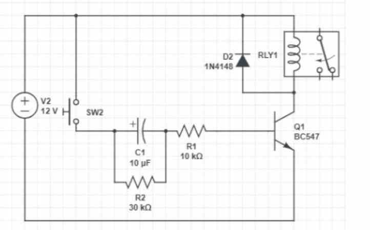
Voltage 12VDC, relay winding resistance 400 Ohm, hfe of the bc547 transistor from 100-800.
I made calculations according to your formula, it turned out to be 300 kOhm.
(in the picture 30 kOhm, I made a mistake).
I have the following task.
– contact SW2 is closed from the soil moisture sensor.
While the capacitor C1 is charging, the transistor is open (I need 1-2 seconds, I probably need to take a smaller capacitor and resistor R1). As soon as the charging stops, the transistor closes.
– is that correct?
Contact SW2 will be closed for 1-2 hours while watering is in progress.
As soon as watering stops (several watering sectors), the power to the sensor is disconnected.
At this point, the capacitor will probably discharge on R2.
– no errors?
Thank you very much, Swagatam!!!
Hi Daniyar,
300k looks too high, you should take the hFE to be 100 and then calculate:
R = (12 – 0.6)100/0.03 = 38000 ohms or 38k, or it can be 33k, 30k is also fine.
Regarding your following question:
– contact SW2 is closed from the soil moisture sensor.
While the capacitor C1 is charging, the transistor is open (I need 1-2 seconds, I probably need to take a smaller capacitor and resistor R1). As soon as the charging stops, the transistor closes.
– is that correct?
The answer is, no that is incorrect, actually it will be just the opposite.
When SW2 is closed, the capacitor starts charging and the transistor and relay are instantly turned ON (hard) and remains turned ON because of the presence of the R2 resistor, as long as SW2 remains closed.
In fact the capacitor C1 serves no purpose in the design.
Please let me know what exactly are you to achieve from the transistor relay circuit, I will try to solve it for you…
Swagatam, good night.
Voltage 12VDC, relay winding resistance 400 Ohm, hfe of transistor bc547 from 100-800.
I made calculations according to your formula, came out 300 kOhm (in the picture 30 kOhm, I made a mistake).
I have such a task.
– contact SW2 is closed from the soil moisture sensor.
While the capacitor C1 is charging, the transistor is open (I need 1-2 seconds, probably I need to take a smaller capacitor and resistor R1). As soon as the charging stops, the transistor closes.
– is everything correct?
Contact SW2 will be closed for 1-2 hours while watering is in progress.
As soon as watering stops (several watering sectors), the power to the sensor is disconnected.
At this moment, the capacitor will probably discharge on R2.
https://drive.google.com/file/d/11NDc_xnJohPdxRTWeWUz-td5f4WRJJ7S/view
– are there any errors?
Thank you very much, Swagatam!!!
Hi Daniyar,
300k looks too high, you should take the hFE to be 100 and then calculate:
R = (12 – 0.6)100/0.03 = 38000 ohms or 38k, or it can be 33k, 30k is also fine.
Your Google drive link is private, please toggle it to sharing, so that it becomes accessible to me and I can open it…
Formüllerinn tamamı yanlış
V=I*R
12-0.6=4/1000*R
R=2850