In this post I have explained the circuit for a simple, universal capacitive discharge ignition circuit or a CDI circuit using a standard ignition coil and a solid state SCR based circuit.
For an audio/video explanation, you can watch the following video representation:
How Ignition System in Vehicles Work
The ignition process in any vehicle becomes the heart of the entire system as without this stage the vehicle just won’t start.
To initiate the process, earlier we used to have the circuit breaker unit for the required actions.
Nowadays the contact-breaker is replaced with a more efficient and long lasting electronic ignition system, called the capacitor discharge ignition system.
Basic Working Principle
The basic working of a CDI unit is executed through the following steps:
- Two voltage inputs are fed to the electronic CDI system, one is high voltage from the alternator in the range of 100 V to 200 V AC, other is a low pulse voltage from a pickup coil in the range of 10 V to 12 V AC.
- The high voltage is rectified and the resultant DC charges a high voltage capacitor.
- The short low voltage pulse drives an SCR which discharges or dumps the capacitor's stored voltage into the primary of an ignition transformer or coil.
- The ignition transformer steps up this voltage to many kilo-volts and feeds the voltage to the spark-plug for creating the sparks, which finally ignites the combustion engine.
Circuit Description
Now let’s learn the CDI circuit operations in detail with the following points:
Basically as the name suggest, ignition system in vehicles refers to the process in which the fuel mixture is ignited for initiating the engine and the drive mechanisms. This ignition is done through an electrical process by generating high voltage electrical arcs.
The above electrical arc is created through extreme high voltage passage across two potentially opposite conductors through the enclosed air gap.
As we all know that for generating high voltages we require some kind of stepping up process, generally done through transformers.
As the source voltage available in two wheeler vehicles is from an alternator, may not be powerful enough for the functions.
Therefore the voltage needs to be stepped up many thousand folds in order to reach the desired arcing level.
The ignition coil, which is very popular and we all have seen them in our vehicles is especially designed for the above stepping up of the input source voltage.
However the voltage from the alternator cannot be directly fed to the ignition coil because the source may be low in current, therefore we employ a CDI unit or a capacitive discharge unit for collecting and releasing the alternator power in succession in order to make the output compact and high with current.
PCB Design
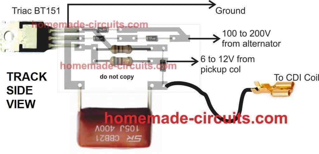
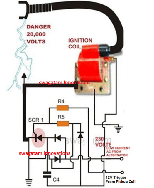
CDI Circuit using an SCR, a few Resistors and Diodes
Referring to the above capacitor discharge ignition circuit diagram, we see a simple configuration consisting of a few diodes, resistors, a SCR and a single high voltage capacitor.
The input to the CDI unit is derived from two sources of the alternator. One source is a low voltage around 12 volts while the other input is taken from the relatively high voltage tap of the alternator, generating around a 100 volts.
The 100 volts input is suitably rectified by the diodes and converted to 100 volts DC.
This voltage is stored inside the high voltage capacitor instantaneously. The low 12 voltage signal is applied to the triggering stage and used for triggering the SCR.
The SCR responds to the half wave rectified voltage and switches the capacitors ON and OFF alternately.
Now since the SCR is integrated to the ignition primary coil, the released energy from the capacitor is forcibly dumped in the primary winding of the coil.
The action generates a magnetic induction inside the coil and the input from the CDI which is high in current and voltage is further enhanced to extremely high levels at the secondary winding of the coil.
The generated voltage at the secondary of the coil may rise up to the level of many tens of thousands of volts. This output is appropriately arranged across two closely held metal conductors inside the spark plug.
The voltage being very high in potential starts arcing across the points of the spark plug, generating the required ignition sparks for the ignition process.
Parts List for the CIRCUIT DIAGRAM
R4 = 56 Ohms,
R5 = 100 Ohms,
C4 = 1uF/250V
SCR = BT151 recommended.
All Diodes = 1N4007
Coil = Standard two-wheeler ignition Coil
The following video clip shows the basic working process of the above explained CDI circuit. The set up was tested on table, and therefore the trigger voltage is acquired from a 12V 50Hz AC. Since the trigger is from a 50Hz source, the sparks can be seen arcing at the rate 50Hz.


Comments
Hello Sir.
Thanks for the answer. If I apply your scheme, TCI with three transistors with a point, I think it should definitely work, but I don’t know how it will be powered.
I believe with the excitation coil (alternator) or I need to add a voltage regulator and battery. If so, what current should I calculate?
Thanks in advance.
Thanks Luan,
which 3 transistor circuit are you referring to, I cannot see any 3 BJT circuit in the above article?
Hello Sir.
I have an Aprilia 50cc motorbike, with a Minarelli V1 engine and a Bosch crankshaft, with 2 coils, 6 volts and an alternator. It also has a point + capacitor. There is no HT coil. The alternator is burnt out with 12,000 turns and I can’t find it. They tell me that it is very difficult to modify. Can you help me with any suggestions. Respect!
Hi Luan,
The original 12,000-turn ignition coil is difficult to replicate accurately. The best option is to convert the system to a CDI-based ignition using an external ignition coil and pickup sensor. This will be more reliable and easier to maintain.
Hi Swagatam
Could you please help me for driving the deuterium Lamp.
Hi Parveen,
Can you please show the datasheet of the lamp, then I can design the full circuit diagram for you…
Or you can just provide the main specifications of the lamp, that will also do…
Need data regarding build of CDI circuit. Desired no reverse in primary coil, and need method of shutting off DC SCR. No second scr or triac. There is charging low value inductor only for CDI capacitor of 2uf. How to stop discharge of power supply filter capacitor to add to the 2uf during main large primary coil discharge. Is separate coil inductor and blocking diode needed for shut off?
You can build the CDI exactly as discussed in the above article, nothing needs to be added or removed…it is a thoroughly tested design, it has been tested on 1000s of 2/3 wheeler automobiles
Hi Swagatam I appreciate your work I’m interested. I will be highly appreciate your advices. Let me have a some time to study. I’m 75+ y. o. Thanks Gentleman
Hi Altaf, no problem at all… wish you all the best with the project…
Dear sir;
What is the power limit of the 100, and 56 Ohm resistors respectively?
Thank you
Hi Jason, they both can be 1 watt rated or above…
Greetings Swagatam
I have two coils on an outboard motor, that needs a CDI unit, because it’s a 2-stroke motor, with 2 sparkplugs. Will this CDI circuit work? Can I connect both the coils to this one circuit?
-Harun
only if you want to trash your engine. if you use te same CDI, your piston cylinders will get fire at the same time, this would most assuredly not run and may even break your crankshaft, there are millions of Artificial Intelligent spider bots spreading disinformation on the internet.
Hi Harun, this CDI is a universal automobile CDI which should work in all types of petrol or diesel engines, provided the trigger pulse input is correctly timed…..
Hi Swagatam
I have built the CDI circuit, and I wanted to know, can you give me some instructions as how to test, with a multimeter, that I have constructed the circuit correctly? Because I’ve tried connecting it to my engine, and nothing happened.
Hi Harun,
You must first test the circuit on your work bench, and then install in your vehicle.
Please do the following set up and confirm the working of the circuit first:
https://www.homemade-circuits.com/wp-content/uploads/2025/10/CDI-test-set-up.jpg
HI, I would like to know the diffrents of a 2 stroke AC CDI to a 4 stroke AC CDI engine? I have a Wisconsin s 14 d engine with the 4 pin AC CDI ign., do you have a CDI circuit diagram for this engine? I tryed a 2 stroke 4 pin AC CDI on this engine and had spark but no run. Any help thanks
Yes that’s correct! 2-stroke CDI gives spark every rotation but 4-stroke engine needs spark only every alternate rotation, during compression stroke only. If you put a 2-stroke CDI on a 4-stroke engine then it may give spark at wrong time (like during exhaust stroke), so engine may fire once but not run continuously.
basically both 2-stroke and 4-stroke engines can use AC type CDI units but the timing and trigger pulse requirements are not same. Even if the pinouts look same and spark comes, the engine might not run, just like what happened to you.
Thanks, Ok the trigger palse is what tells the condenser to release the stored energy to the ignition coil. The timming is fixed to fire BTC on both 2 and 4 stroke engines, what is the diffrents in the AC CDI ?
AC and DC CDIs both work in the same way, there job is to discharge a high voltage capacitor to generate a spark. AC CDI uses high voltage AC from the alternator, whereas DC CDI can use 12V from battery and boost it to generate a high voltage pulse using an internal transformer.
Thanks, What I wanted is to know what’s inside the AC CDI box that makes 2 stroke and 4 stroke diffrent? To make a CDI for a Wisconsin engine, would I have to be an wisconsin engineer?
inside AC CDI for 2-stroke and 4-stroke almost all components are same, they have high voltage capacitor, SCR, trigger circuit, etc. What makes them different is mostly how the trigger timing is set up because 2-stroke needs spark every 1 turn, 4-stroke needs spark every 2 turns. Some CDIs are smart and skip every second trigger but most just follow whatever trigger you give. So if you use a 2-stroke CDI on 4-stroke engine then it may give spark on exhaust stroke also (called wasted spark), not harmful but not best. About your Wisconsin engine, you do not need to be a Wisconsin engineer, you just need to check how many magnets on flywheel, where is the pickup coil, what spark timing is needed and then match a CDI to work with that pulse. You can use ready-made CDI or even build one if you know SCR circuits.
like to make a circuit CDI discharge system.
discharge will be at 2000VDC , 12 jule power , 2-3 discharges per sec.
Input voltage 220 V /120 V AC,
please comment
Sure, you can try the above CDI circuit, the sparking frequency will depend on the triggering frequency at the “pickup coil” input terminal of the circuit…
kondensaattori sytyksen lisääminen esim boch käjettömäänn sytys järjestelmään? Palkoko maksaa.MSD A6 on kallis voiko vastaavan tehdä halvemmalla.
greetings Swagatam
I made this once but it didn’t work, I think I made a mistake somewhere,I wanted to know if this circuit is CDI, DC or AC?
thanks for sharing
Hi John, did you supply the 100V to 200V high AC voltage and the 12V pulsed voltage to the inputs of the CDI circuit as shown in the diagram?
Both of these voltage simply needs to be pulsed, it doesn’t matter whether they are AC or DC, they should be intermittent and not continuous, that’s all…please let me know.
Hi Swagatam thanks for reply,
When I made it again I saw that it worked very well, I must have been wrong before, it was really great, thanks
Can you share CDI racing or DC circuit?
And instead of bt 151 thyristor, can I use z44 MOSFET or 2n 3055 transistor?
how can I make a simple unit to trigger a cop coil on my motorcycle
That’s great John, glad it is working now!
For a DC CDI you can refer to the following article:
https://www.homemade-circuits.com/make-this-enhanced-capacitive-discharge/
No, I don’t think the SCR can be replaced with a transistor, SCR looks more suitable for this specific application.
helow sir i wish to have a 4pin cdi diagram..can riv to high rpm hopefully
Hi Mark, can you please provide the specifications of the 4 pins, I will try to help!
Hi, have you tried using this circuit with a square wave DC pulse as the trigger? I am using a similar design, although slightly simpler, only a current limiting resistor to the gate pin instead of a divider and slightly higher capacitance on the capacitor, but basic idea still remains. However I ran into a weird issue of it not revving past 1500 rpm.
Hi, It doesn’t matter whether the triggering pulse is a square wave or a sine wave, the SCR will trigger once the gate voltage crosses the 0.7V mark.
You can try the above design and check if it makes any difference.
Cool I just blew out my cdi on moped and I have no income but I got ability and some junk parts I can salvage all I needed was your information to build replacement cdi and get going again. And I noticed your section HHO which I believe has to do with hydrogen if I’m correct I want to make all my power come from hydrogen and the greatest fuel in world only thing I’ve been stifled by is coming up with easy free supply for electrolyte. But your just the help inspiration I needed book marked¡¿¡
Sure, I can help. If you have CDI related questions you can ask them here. For the HHO related questions you can feel free to comment under the following article:
https://www.homemade-circuits.com/how-to-use-hho-fuel-cell-in-automobiles/
Ya know I looked at that circuit and thought it looks to me like it could take reverse 20 volt except cap and I was right but the regulator was bad and I believe it was in need replaced b4 cool ty for simple circuit
can i use MOSFET irfz44n insted scr by151
No, MOSFET cannot be used in place of SCR.
Sir, Is there a way to modify or add a timing adjustment to the cdi circuit. auto or manual??? thanks Nick
Sir, question about how to wire the cdi,, wire that goes to the alternator.. my magneto, has 3 wires coming from engine alternator coil, 18 total coils ,with. six,6 coils per wire 2011 suzuki savage 650 motorcycle. they run to a rectifier . How do I connect the single wire coming from cdi to the 3 wire magneto??? hope i made this clear.. thanks for any assistance. Nick in Missouri.
Hi Nick,
As far as I know, you will need to check the voltages from the respective alternator wires with respect to the body ground of your motorcycle. You may have to use an AC voltmeter to check this.
The wire that produces anything above 100V AC can be connected to the CDI 230 V input.
The 12V trigger input from the CDI must be connected with the pickup coil output of your motorcycle.
I think a good qualified motor mechanic or electrician will be able to guide you better regarding the relevant connections.
Thanks for a swift reply. Great job. I Understand, I think I can figure it out. 5 plus. Nick
Glad I could help!
Hi Nick, sorry, in this basic CDI circuit design, timing adjustment cannot be added.
thank you so much for your circuits and your help. Nick Carper
Dear all
can you peaple give me a DC CDI Circuit for 200cc motor bike it will be very helpful
Thank you all for informations.
Hello Padmaharsha,
you can build the CDI circuit explained in the above article, it is perfectly suitable for you bike…
thanks for your answers to my inquiry. Yes I have a trigger coil that is working … Suzuki 2011 savage 650 single cylinder.