TSOP17XX series devices are advanced infrared sensors having a specified center frequency of operation which makes their detection extremely reliable and foolproof.
In this post I have explained how to connect a TSOP series infrared sensor and use it for a specified IR remote control operations.
TSOP IR Sensor Specifications
A TSOP series of IR sensor ICs may consist many variants which differ marginally from each other, these may be in the form of TSOP22.., TSOP24.., TSOP48.., TSOP44..
However the most popular and most commonly used is the TSOP1738 IC module which is from the TSOP17XX series.
The other variants from this group are available with the following numbers:
TSOP1733, TSOP1736, TSOP1737, TSOP1740, TSOP1756, TSOP1738CB1, TSOP1738GL1, TSOP1738KA1, TSOP1738KD1, TSOP1738KS1, TSOP1738RF1, TSOP1738SA1, TSOP1738SB1, TSOP1738SE1, TSOP1738SF1, TSOP1738TB1, TSOP1738UU1, TSOP1738WI1, TSOP1738XG1, TSOP1740, TSOP1740CB1, TSOP1740GL1, TSOP1740KA1, TSOP1740KD1, TSOP1740KS1, TSOP1740RF1.
All the above TSOP variants have identical features and characteristics except their center working frequency, which may typically range between 30 kHz to 60 khZ.
How the Connect TSOP1738 sensors
Connecting or wiring a TSOP1738 infrared sensor is actually very easy, once you know how it responds to supply voltage and the IR signals applied across its specified pinouts.
The diagram below shows the a standard TSOP infrared sensor IC, whose pinouts can eb seen marked as (-), (+) and the OUT.
The (+) and the (-) are the supply pins of the IC and are specified to be connected across a 5V typical supply level, to be precise any voltage between 3 and 6V may be aplied here, although 5V works the best, and is recommended since it can be easily tailored using a 5V regulator IC 7805 and allows a wide range of input to be used (between 6V and 24V).
The curved lens which can be seen over the central portion of sensor body is where the infrared signal from a remote control handset is focused for enabling the TSOP to initiate its sensing operations.
TSOP1738 Sensor and IC 7805 Pinout Details
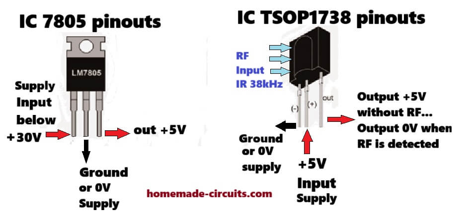
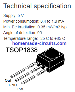
NOTE: The pinout polarity is different for the TSOP1838 IR detector, as shown below. So please verify the pinout sequence if you are using a different variant of the IC.
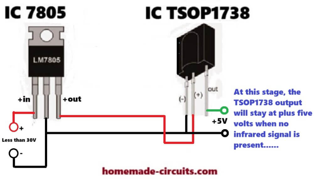
How connect Supply Voltage to TSOP1738
The following image shows how the TSOP1738 IC needs to be wired and connected across a +5V supply voltage and how its output may respond in the presence and absence of a 38kHz IR (infrared) signal input...
How TSOP1738 Responds to Infrared Signal
I have explained step wise how a wired TSOP1738 sensor behaves or responds when an IR signal is focused towards its lens.
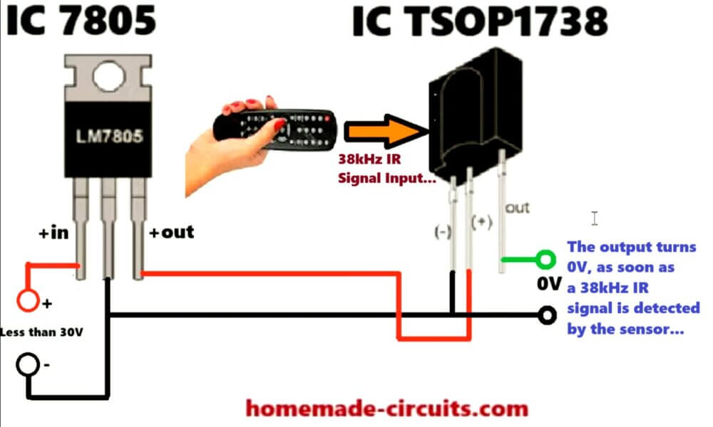
The TSOP1738 IC output stays at high +5V as long as there's no 38kHz IR signal being applied to its sensor lens surface. However as soon as a 38kHz IR signal is detected on its sensing lens surface, its output quickly turn into a 0V output.
Video Clip
Initially the Output is a +5V (Supply Level)
As soon as the TSOP is applied with a supply voltage (via a 5V regulator), it responds by making its output pin high or at the positive (+5V) level.
This level is maintained, as long as an input infrared signal is not pointed or is focused towards the lens of the TSOP
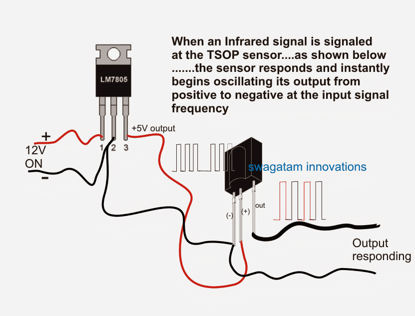
When an IR Signal is Applied
In the above diagram we can see IR signal frequency being applied and approaching the lens of the TSOP, until it touches the lens of the sensor.
The moment the IR signal reaches the lens of the TSOP, the output of the TSOP begins responding and oscillating in tandem with the focused infrared signal.
Remember, the input IR frequency focused towards the TSOP sensor must be oscillated at a 38 KHz frequency, otherwise the TSOP sensor will not respond. This frequency may be slightly different for the different variants of the TSOP sensors.
The Output Waveform of the Sensor
The output waveform indicates how the output of the IC oscillates between a positive (initial status) and negative (sensing status) across its "OUT" pins in an alternating pattern, as long as the input IR is kept focused towards it.
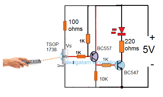
How to configure the above response from the TSOP1738 sensor for driving a relay stage.
A classic example may be seen in the following diagram taken from the article "remote controlled fish feeder", where we can see the TSOP being used for an IR remote control application and for a toggling action in response to an IR input triggering signal.
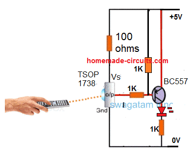
Basic Connection Details of TSOP1738 in a Circuit
Simplified Design
Application Schematic for TSOP1738 Relay Operation
Parts List
- R1, R3 = 100 ohms
- R4, R2 = 10K
- T1 = BC557
- T2 = BC547
- Relay 12V, 400 ohms
- IC = 7805
- D1 = 1N4007
- Sensor = TSOP17XX
- C1, C2 = 22uF/25V
Here we can see that a PNP transistor is being used for toggling the relay, I have explained why exactly a PNP device is required for toggling a TSOP sensor, why an NPN BJT may not be suitable for the same.
Through the above explanation we understood the fact that while the TSOP is in the standby mode or as long as there's no IR signal focused, the output from the device holds a positive potential.
This implies that if an NPN was used in conjunction with this output then this would force the transistor to remain switched ON in the standby mode, and switch it OFF in the presence of an IR signal....
This is technically incorrect because this would keep the relay switched ON all the time and switched OFF only while an IR signal was triggered...this condition is not recommended and therefore we use a PNP transistor which inverts the response from the TSOP sensor and toggle the relay ON only in response to an IR signal, and keeps the relay switched OFF normally while the sensor is in the standby mode (no IR signal).
Here C2 is used to filter the ripples or the pulsating DC output of the TSOP, so that the transistors activate properly and without causing a chattering effect on the relay


Comments
Also yesterday,you replied me to use t2 as bc547.but that comment is removed.waiting for your reply
Sorry Nived I am facing some problems with my site, therefore there may be some issues for the moment, by the way I have corrected the the BC557 with BC547
Hi sir,
I made the relay based circuit ,but the problem is that the relay keeps on triggering.When i use the remote,triggering stops.when i move the remote away,it again starts triggering
You mean, the relay stays ON when the remote is not activated? and OFF when the remote is activated…
Exactly sir,
Relay keeps on trigering.when the remote is activated,it stops.like that
Nived, the relay should switch ON only when remote is shown towards the sensor. Connect an LED in series with R4 this will tell you how the circuit is responding.
The sensor output iis supposed to go low when IR is present from remote, and will remain high in the absence of IR (no signal). BC557 will switch ON only when the sensor is low.
dear sir
i want to make IR beam barker alarm circuit.
it means IR beam continuously fall on the TSOP and the relay to be on, if some one cut the IR beam
request instructions for circuit
thanks
Jayanth,
you can try the following concept:
https://www.homemade-circuits.com/remote-controlled-fish-feeder-circuit/
for the transmitter you can use an IC 555 based astable set at 38kHz frequency, and connect any photodiode across its pin#3 and ground, then focus the beam on the TSOP sensor…make sure to add a 470 ohm resistor in series wit this LED
sir i have gone through above fish feeder circuit. but,, in my concept ir beam continuously fall on the tsop and i want to switched the relay when ir beam disturbed. i already made 38khz circuit also. any alteration to fish feeder mechanism circuit?
Jayanth, you can keep the 38kHz beam continuously focused on the TSOP, no alteration would be required since it is exactly as per your requirement.
yes sir but relay is always in contact. and relay will be disconnect i\only when ir beam is interrupted. that will effect to the relay coil during long time operation. so want to relay to be contact only when ir beam is interrupted sir. request instructions
ok sir thank you i will do that
dear sir
circuit is working fine. thanks sir. And also i want to latch the output. i mean when some one breaks IR beam the relay to be in contact till power off.
That’s great jayanth,
to latch you can connect a diode between the base of the middle BC547 and the collector of the relay driver BC547. Cathode will go to the collector.
Also connect a 1K resistor across the base and ground of the middle BC547 transistor.
But remember, with this arrangement the circuit will be latched initially when power is switched ON. You must have switch in series with this diode so that you can keep the diode disconnected initially and switch it ON only once the IR beams is correctly focused on the TSOP.
sir i have made it . it is working perfectly with abans tv remote. but it is too sensitive. i have to fully block the IR led by finger , to cut the beam. how to decrease the sensitivity of TSOP ?
Hi Jayanth, try enclosing the TSOP inside an opaque pipe, such that the transmitter beam is able to hit the sensor only when it is aligned with the mouth opening of the pipe. In this way you might be able to achieve the desired results.
ok sir i will do and reply you
Jayanth, for this you can do the following modifications:
remove the relay from the existing position and replace the points with a 10K resistor.
take another BC547 transistor, connect its base with the existing BC547 collector, emitter with the ground line, and now connect the relay across this new BC547’s collector and the positive line.
Make sure to add the 1N4007 with the relay coil.
this will invert the switching condition as desired by you.
Where is the parts list ?
updated now!
Hi
I am planing to do some simple project with tsop sensor interfacing to 8051 controller. Here we are using like TV remote, for each button in remote, am planing to do some task, how can i read the each button of remote values to write program
Hi, if it's possible I'll try to post the details it in this website soon…
PLEASE HOW CAN I KNOW WHEN THE TSOP DEVICE IS BAD. ARE THERE DIFFERENT WAYS OF CONNECTING OTHER TSOPS APART FROM THE METHOD YOU HAVE PRESENTED
there's only one way of connecting these ICs as illustrated in the above diagrams. check the output voltage in response to a IR beam input…