In this post I have explained how to correctly connect an IR photodiode in circuits such as a proximity sensor circuit. The explanation is presented in the form a discussion between one of the dedicated readers of this blog NVD, and me.
Here's the discussion which explains how to connect a photodiode in an electronic circuit.
Verifying IR Photodiode Connection in a Circuit
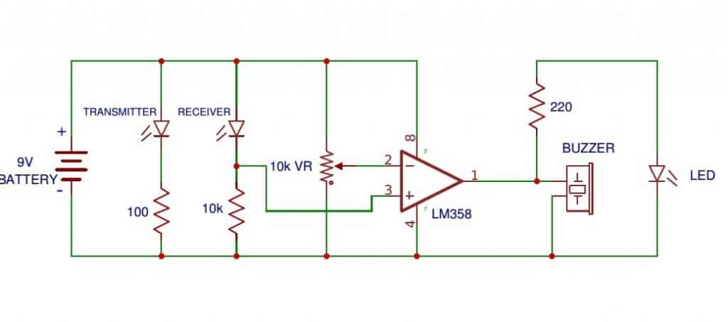
Question: Can you please tell me whether following circuit work or not. I think output of ic is 5v. I want the output to be connected to a 12v relay instead of buzzer..can you tell what alterations should i make in the circuit..
Analyzing the Circuit
Answer:
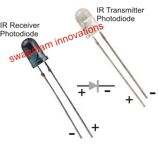
(+) is the Anode, and (-) is the Cathode of the Photodiode. In other words the pin associated with the wider plate inside the photodiode will be be the Cathode, and the pin associated with the thinner plate inside the photodiode will be the Anode
- if it's set correctly then it should work..However the diagram above has many mistakes and will never work. The IR photodiode configuration with the opamp will need some modifications.
- For configuring a relay, you can use a BC547/relay stage at the output of the opamp, the base resistor cold be 10K
- For a details information regarding the relay driver stage you can refer to the following article: https://www.homemade-circuits.com/2012/01/how-to-make-relay-driver-stage-in.html
Question:
ok is there any positive and negative terminal for IR receiver and transmitter like led. I'm new to to this, that's why asking
Polarity for IR Photodiodes in Transmitters
- just like any other diode, IR photo-diodes also have polarity and must be connected accordingly.
Question:
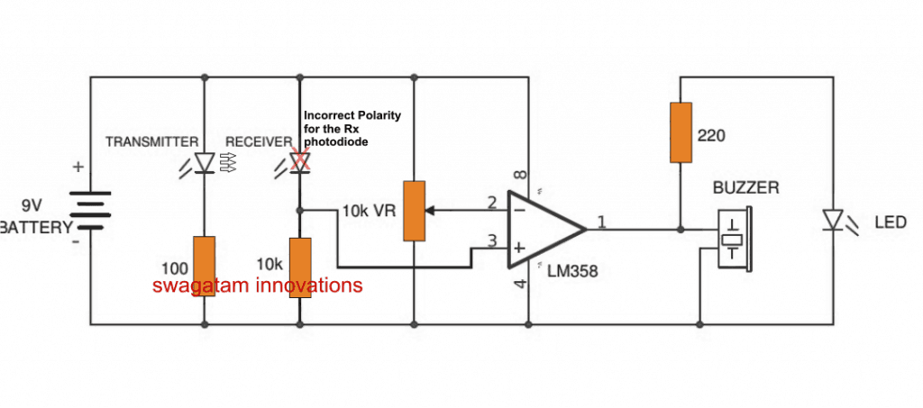
In the circuit, photodiode is connected forward bias. is it wrong? Please check sir.
Circuit Diagram
IR Photo Polarity for Receiver
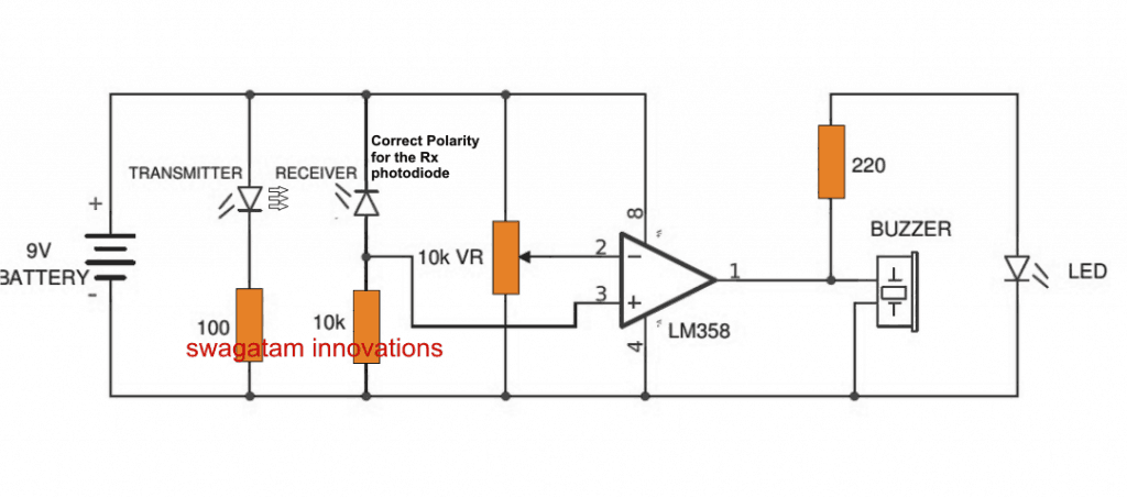
- The transmitter IR photodiode polarity is correct...receiver polarity is wrong, needs to be inverted for the receiver as shown below.
Question:
sir, firstly i forgot to connect IC pin 3 to receiver resistor then i have given a supply of 12V therefore Led lights up only. After that I connected pin 3 to resistor and given 9V. Now led lights when i turn the variable resister to one side. LED doesn't light up when obstacle is brought in front.
Can an IR Photodiode get Burnt
I connected everything properly still it doesn't work, is there a chance of IC or photodiode getting burnt when i connect to a 12V supply. Do you have any circuit diagram for IR proximity sensor.
Please help me sir.
Answer
- The photodiode will never burn as long as its connected in series with a resistor.
So why is the Receiver Photodiode not Responding
Answer:
In the diagram above the photodiode connected with the opamp will never be able to trigger the opamp in response to a received infrared signal, Why??
The Right way to Connect a Photodiode with an Opamp
The voltage generated by the receiver photodiode in response to the signals from the transmitter photodiode will be hardly in millivolts, may be just a couple of millivolts.
Although opamps may be sensitive to detect even to a couple of millivolts, the 10K resistor across pin#3 and ground will instantly nullify the tiny millivolt signal making it impossible for the opamp to detect it.
Therefore we can assume that it is the 10K resistor that is responsible for not allowing the opamp to detect the photodiodes output signal.
The following diagram shows how to connect a photodiode correctly with an opamp such that it effectively responds to the signals from any IR photodiode transmitter source:
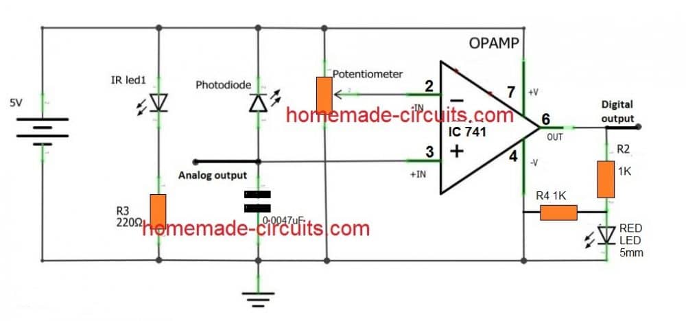
In the above diagram we can see that the earlier 10k resistor at the non-inverting pin of the opamp is replaced with a low value capacitor, and now this allows the opamp to respond to the signals generated from the Rx, Tx photodiodes.
In fact the opamp would still respond without the capacitor, however it is never advisable to keep the inputs of an opamp floating while it is powered, therefore the grounded capacitor makes sure that the concerned input of the opamp never stays floating and prone to stray signals.
You may think that the capacitor could be replaced with a high value resistor, in the order of many Meg Ohms, sorry that might not help either, that would again prohibit the opamp from sensing the signals from the photodiode, and ultimately the low value capacitor results in being the right choice.
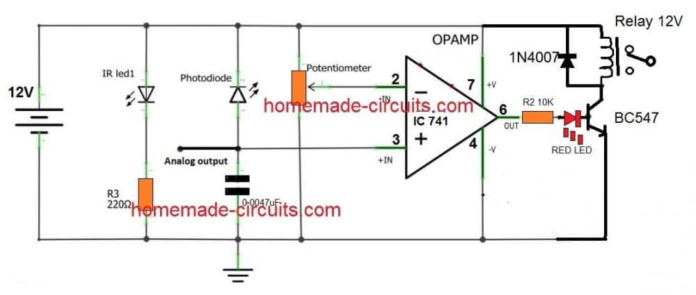
Connecting Photodiode for Activating a Relay
The above shown opamp based photodiode detector can be further upgraded to trigger a relay stage by integrating a relay driver stage as shown in the following diagram:
Feedback from Mr. Norman Kelley (one of the avid readers of this blog):
Hi, Swagatam,
I have been looking for a circuit to alert me when someone enters my courtyard and front deck.
Delivery people leave things on the front deck and do not ring the door bell, so I don't know my packages are on the deck. Also, at night, I would like to know if someone enters my courtyard.
I designed a circuit with a PIR and a wireless TX/RX to play a message inside my house. Everything works but there are many false triggers and it drives my wife nuts.
I am assuming that the RF signals are triggering the PIR. I tried separating them a few inches and it helped, but not enough. So, I decided to look at IR to detect the person opening the gate to the courtyard and then wirelessly transmitting that trigger. I wanted to do an IR beam, but it requires more components that I don't have at this time.
So, I decided a proximity IR would work if I placed the sensor at the gate and put a reflector on the gate that would reflect the IR when the gate was opened.
I saw your above circuit "How to connect an IR Photodiode Sensor".
I bread boarded the circuit and it works fine. The only problem is it uses 50ma in standby mode and 70ma when active.
Remote mounting with battery power supply seems to be out of the question unless there is a way to reduce the power requirements or I will have to run low voltage out to the unit.
Any suggestions or comments? Thanks for your help!
Norman Kelley
My Response:
Hi Norman,
The high consumption could be simply due to the incorrect LED resistor values, try using 1K for transmitter LED and also for the indicator LED, the total consumption should come down to around 6mA


Comments
Is it possible to substitute the battery with a 5v VCC? If so, what will the required resistor needed to be?
Regards,
Wending
sir
can you please tell me whether this circuit works or not
https://drive.google.com/open?id=0B-dWJVKXq45-SVEtdGF5MlRRaE0
Raj, It might work if the BC557 is a Darlington transistor, and also it is incorrectly presented as an NPN…correction is required.
use 10K
yes, you can replace the buzzer with a relay driver stage as I have explained below
https://www.homemade-circuits.com/2012/01/how-to-make-relay-driver-stage-in.html
Fantastic works
thank you