In this post I have explained how to construct a simple solar panel regulator controller circuit at home for charging small batteries such as 12V 7AH battery using small solar panel
Using a Solar Panel
We all know pretty well about solar panels and their functions. The basic functions of these amazing devices is to convert solar energy or sun light into electricity.
Basically a solar panel is made up with discrete sections of individual photo voltaic cells. Each of these cells are able to generate a tiny magnitude of electrical power, normally around 1.5 to 3 volts.
Many of these cells over the panel are wired in series so that the total effective voltage generated by the entire unit mounts up to an usable 12 volts or 24 volts outputs.
The current generated by the unit is directly proportional to the level of the sun light incident over the surface of the panel.
The power generated from a solar panel is normally used for charging a lead acid battery.
The lead acid battery when fully charged is used with an inverter for acquiring the required AC mains voltage for powering the house electrical. Ideally the sun rays should be incident over the surface of the panel for it to function optimally.
However since the sun is never still, the panel needs to track or follow the suns path constantly so that it generates electricity at an efficient rate.
If you are interested to build an automatic dual tracker solar panel system you may refer one of my earlier articles.
Without a solar tracker, the solar panel will be able to do the conversions only at around 30 % efficiency.
Coming back to our actual discussions about solar panels, this device may be considered the heart of the system as far converting solar energy into electricity is concerned, however the electricity generated requires a lot of dimensioning to be done before it can be used effectively in the preceding grid tie system.
Why do we Need a Solar Regulator
The voltage acquired from a solar panel is never stable and varies drastically according to the position of the sun and intensity of the sun rays and of course on the degree of incidence over the solar panel.
This voltage if fed to the battery for charging can cause harm and unnecessary heating of the battery and the associated electronics; therefore can be dangerous to the whole system.
In order to regulate the voltage from the solar panel normally a voltage regulator circuit is used in between the solar panel output and the battery input.
This circuit makes sure that the voltage from the solar panel never exceeds the safe value required by the battery for charging.
Normally to get optimum results from the solar panel, the minimum voltage output from the panel should be higher than the required battery charging voltage.
Meaning, even during adverse conditions when the sun rays are not sharp or optimum, the solar panel still should be able to generate a voltage more than say 12 volts which may be the battery voltage under charge.
Solar Voltage regulators available in the market can be too costly and not so reliable; however making one such regulator at home using ordinary electronic components can be not only fun but also very economical.
You may also want to read about this 100 Ah Voltage Regulator Circuit
Circuit Diagram
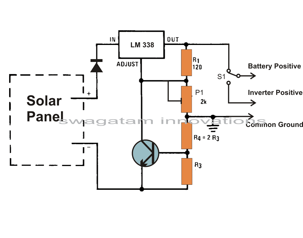
NOTE: PLEASE REMOVE R4, AS IT HAS NO REAL IMPORTANCE. YOU CAN REPLACE IT WITH A WIRE LINK.
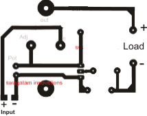
Track side PCB Design (R4, Diode and S1 not included...R4 is actually not important and may be replaced with a jumper wire.
How it Works
Referring to the proposed solar panel voltage regulator circuit we see a design that utilizes very ordinary components and yet fulfills the needs just as required by our specs.
A single IC LM 338 becomes the heart of the entire configuration and becomes responsibly for implementing the desired voltage regulations single handedly.
The shown solar panel regulator circuit is framed as per the standard mode of the IC 338 configuration.
The input is given to the shown input points of the IC and the output for the battery received at the output of the IC.
The pot or the preset is used to accurately set the voltage level that may be considered as the safe value for the battery.
Current Controlled Charging
This solar regulator controller circuit also offers a current control feature, which makes sure that the battery always receives a fixed predetermined charging current rate and is never over driven. The module can be wired as directed in the diagram.
The relevant positions indicated can be simply wired even by a layman. Rest of the function is taken care of by the regulator circuit.
The switch S1 should be toggled to inverter mode once the battery gets fully charged (as indicated over the meter).
Calculating Charging Current for the Battery
The charging current may be selected by appropriately selecting the value of the resistors R3.
It can be done by solving the formula: 0.6/R3 = 1/10 battery AH The preset VR1 is adjusted for getting the required charging voltage from the regulator.
Solar Regulator with Adjustable Voltage and Current Output
The following figure shows a high current voltage regulator circuit using the LM338 ICs.
The high current is achieved by connecting many number of LM338 Ics in parallel over a single common heatsink.
The parallel LM338 are not shown in diagram but while building it practically you can connect at least 8 numbers of LM338 ICs in parallel.
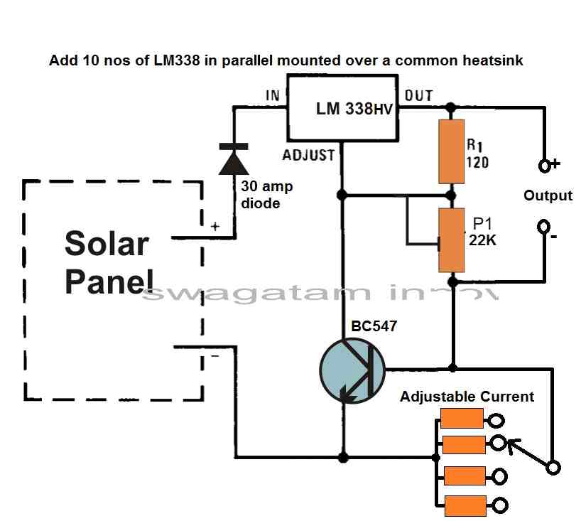
The input voltage can be as high as 50 V if LM338 HV IC is used.
The BC547 transistor is used for current control by adjusting the resistance at its base using a resistor ladder.
When many LM338 ICs are linked in parallel, the load current may be shared, enabling the circuit to tolerate larger currents.
As per the rules it is vital to remember that the output voltage of each IC may not be precisely the same, resulting in uneven load current sharing.
To avoid this, connect a tiny resistor (such as 0.1 ohms) in series with each IC's output to equalize current sharing.
However, as we have already mentioned that the ICs must be connected over a single common heatsink so that the heat dissipation can be shared and the ICs conduct equally. Therefore, adding a 0.1 ohm resistor may not be critical.
The BC547 transistor connected to the ADJ pin of the LM338 acts as a current sink for the IC, allowing the current to be adjusted by changing the resistance at the base of the transistor.
The resistor ladder connected to the base of the transistor allows for easy selection of the desired current level.
Overall, this circuit provides a high current, adjustable voltage regulation solution using the LM338 ICs in parallel.
However, it's important to ensure that the heatsink can handle the heat dissipation of multiple ICs operating at high currents to prevent thermal issues.
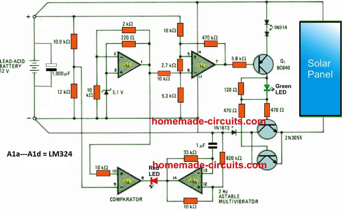
Solar Regulator using IC LM324
For all solar panel systems, this single IC LM324 based guaranteed efficient regulator circuit offers an energy-saving answer to charging batteries of the lead-acid type typically seen in motor vehicles.
Not taking into consideration the price of the solar cells, believed to be in front of you for use in various other plans, the solar regulator on their own is below $10.
As opposed to a number of other shunt regulators that will redirect current through a resistor once the battery is completely charged, this circuit disconnects the charging supply from the battery eliminating the need of bulky shunt resistors.
How the Circuit Works
As soon as the battery voltage, is under 13.5 volts (usually the open-circuit voltage of a 12 V battery), transistors Q1, Q2, and Q3 switch on and charging current passes through the solar panels as intended.
The active green LED shows the battery is getting charged. As the battery terminal voltage nears the open-circuit voltage of the solar panel, op amp A1a switches OFF transistors Q1-Q3.
This situation is latched for so long as the battery voltage drops to 13.2 V, whereafter the triggering of the battery charging process is again restored.
In the absence of a solar panel, when the battery voltage keeps dropping from 13.2V to roughly 11.4 V, implying a totally discharged battery, A1b, output switches to 0V, triggering the attached RED LED to blink at a rate fixed by the astable multivibrator A1c.
In this situation blinking at a rate of 2 hertz. Op amp A1d gives a reference of 6 V to retain the switching thresholds at the 11.4 V and the 13.2 V levels.
The proposed LM324 regulator circuit is designed to cope with currents up to 3 amperes.
To work with more substantial currents, it may be essential to make the Q2, Q3 base currents higher, to ensure that all these transistors can maintain saturation throughout the charging sessions.
Solar Panel Regulator Circuit using IC 741
The majority of typical solar panels provide around 19V off load.
This enables to get a drop of 0.6V over a rectifier diode while charging a 12V lead-acid battery. The diode prohibits battery current from moving via the solar panel during night.
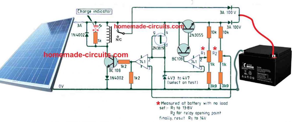
This set up can be great so long as the battery does not get overcharged, since a 12V battery can easily become overcharged to above 1V5, in case the charging supply is not controlled.
Voltage drop induced through a series pass BJT, typically is approximately 1.2V, which appears to be way too high for nearly all solar panels to operate effectively.
Both the above flaws are effectively removed in this simple solar regulator circuit. Here, energy from the solar panel is supplied to the battery via a relay and rectifier diode.
How the Circuit Works
When battery voltage extends to 13.8V, the relay contacts click, so that 2N3055 transistor begins trickle charging the battery to a optimum of 14.2V.
This full charge voltage level could be fixed a bit lower, despite the fact that most lead-acid batteries start gassing at 13.6V. This gassing is significantly increased at overcharge voltage.
The relay contacts operate the moment battery voltage drops under 13.8V. Battery power is not utilized to operate the circuit.
The fet serves like a constant current source.
Shunt Type Solar Voltage Regulator Circuit
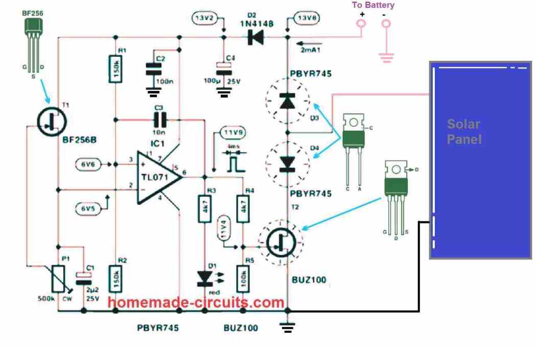
The shunt type solar panel regulator circuit shown above can be understood with the following points:
The op amp TL071 is configured like a comparator.
The FET BF256 along with the 500k preset P1 forms a constant current and constant voltage reference generator for the inverting input of the op amp.
THe pin3 which is the non-inverting input for the op amp is held with varying voltage source depending on the level of the battery terminal voltage, therefore this pin3 works like the over charge sensing input of the compartaor op amp.
The preset P1 at pin2 of the IC is adjusted in such a way that the potential at pin3 input of the IC is just higher the pin2 as soon as the battery reaches the full charge level.
While the battery level is below the full charge value, the potential at the pin3 is lower than the pin2 which keeps the output of the op amp to zero logic, and the FET T2 BUZ100 remains switched OFF.
However, as soon as the battery reaches the full charge level, the pin3 potential now increase above the pin2 value, which causes the output of the op amp to change state to a high output.
This immediately switches ON the FET T1, which shunts the solar panel voltage to ground, thereby preventing any further charging of the battery.
While the solar panel voltage is being shunted by the FET T1 via the diode D4, these two devices can get substantially hot, since the whole solar panel power gets grounded by these two devices.
The diode D3 ensures that once the battery is charged, it never gets discharged through the solar panel, especially during the night time.
The LED D1 indicates when the battery is fully charged and cut off, as it gets switched ON.
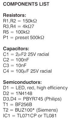
Parts List


Comments
Hi Swagatam,
Any amendments to the circuit required for Lithium batteries?
Hi Chris, for lithium batteries you just have to adjust the voltage and current appropriately, using the same concept:
https://www.homemade-circuits.com/wp-content/uploads/2023/05/36-V-high-current-solar-regulator-circuit-with-adjustable-current-facility.jpg
Voltage should be at around 4.1V each cell, and max current 50% of the Ah rating…
I have just had a voltage regulator installed on my 4Kw solar panels as i didn’t think i was generating enough energy to my watt meter where i take my readings. I dont know if that will improve my totalise readings! I don’t have bateries on my system.i was wondering if it was necessary to fit this unit or have i been conned into fitting this unit which is supposed to stabalise the voltage to my invertor or stop interaction between it and grid voltage
Regards Robert.
If it is an MPPT regulator or a buck converter regulator then it will definitely improve your panel output power.
Hi if the voltage out of the solar panel inverter and onto the house dis board is the same voltage level as what the grid is supplying then is it accurate to say that there is no potential difference so if the house is using 10amps then this will be 5amps from solar and 5amps from the grid. Also if the solar panel voltage is the same as the grid how can the solar panel supply current into the grid as againbhhere is no potential difference to allow any current to flow.
Hi, I am actually not very sure, I think the grid AC being more powerful than the solar inverter, it will alone supply all the power to the load, and no power will be extracted from solar inverter. The inverter power will be consumed only once the grid voltage begins to drop.
I have a 5.4 kw solar array on my house generating 240v activated by PGandE voltage. No battery system. It is tied to my house panel. If PGandE goes down. I lose power. No sychronizing voltage. I also have a gas 6kw generator that I can connect to my house panel through a transfer switch. It could provide sychronizing voltage that would activate my panels. However, I have been told that would destroy all electrical devices in my house. I don’t want to buy a Tesla power wall to regulate the voltage. Any suggestions.
I did not understand what you meant by: “It could provide synchronizing voltage that would activate my panels…”
Do you mean the generator voltage would replace the panel voltage?
If this is done with proper isolation through a changeover relays, then I do not see why your electrical devices could get damaged?
Ok sir , I will match the coil ( removed and taken from other cooker circuit 2000watts ) and capacitor is resonance at 25Khz. I will measure its frequency before removing it. Then using yours IR2153 circuir I will connect it to a 300 watts 36V ( 100w-12V X 3 nos series) solar panel directly . There will be no other circuit or user interface or display. Let us see. I have decided to go ahead with this test. I will give you the result. It will take some time. I hope very much that it should work else I will make my coil and operate it at resonance.
J K barik
No problem jk, hope it works for you, wish you all the best!
But I will use separate circuit ( yours IR 2153) but same coil and capacitor of 2000watts cooker.
Same frequency. Current is reduced so I should get low power.Why not?
That is not possible, every circuit has its own matching coil/capacitor….you cannot use a different capacitor set up with some other circuit.
If you want to reduce wattage, just reduce the input current, without changing the voltage. So if you want to reduce 2000 watts/300V circuit to 200 watts, then you can probably use a 300 V, 0.7 amp solar panel.
Inside a 2000watts induction cooker the coil works with 300V dc and 25Khz. If I give 30V dc from solar panel then will it give 200 watts ?
I don’t think so it will work with 30V, because there’s a huge difference between 300V and 30 V, and the circuit is designed to work with high voltage so a 30% to 40% reduction can be managed but not this much. But there’s no harm in trying it
I would rather not go with a Mppt.
I am putting 3x 50w 12v (17.6 vmp) solar panels in series on my ebike solar trailer to charge my 36v Li-on 12Ah battery. Can you show me a simple circuit that would prevent the battery from over charging.
I also have a second bike with a 48 volt 14Ah battery and I will be putting 4x 50w (17.6 vmp) solar panels in series on that one.
The last circuit is the one which suits your requirement perfectly. You can try that….for 3 panels you may have to use 3 MOSFETs (T2) in parallel, and same must be done with the D3 D4….just make sure to clamp the parallel devices over a common heatsink, individually for all the 3 devices.
However the IC can withstand at the most 36 v…so you may want to add a 35 V zener diode across the pin7 and pin4 of the IC…and also add a 1K 2 watt resistor in series with D2
Hi!
Fell over your site, hunting cheap and DIY made solar panel regulators.
I have a panel 15 W 18-20 Volt and I will charge a battery 12 Volt 14Ah AGM. Just curious, if I can only use the voltage regulation with LM338, without the current regulation. My calculation for my batter would be charging current of 1.4 A and that should be a resistance of 0.43 ohms, Correct?
If I don’t use the current regulation, then the solar panels max current (most bright sun and angel), should go to the battery? I don’t think the solar panel can exceed 1.4A Correct?
So for AGM 12 Volt and +22°C I should set the voltage regulator for 14.4 – 14.6 Volt. Correct?
Regards
Ham operator SM6GZL
Hi,
your assumptions are correct, since the solar panel cannot produce more than 1.4 amps, your battery is safe from over current, under all circumstances.
The result 0.43 ohms as calculated by you is also correct in case you use the specified current limiting feature.
Just make sure to adjust the LM338 output voltage to 14V which will ensure that your battery remains safe even without an over charge cut-off facility
Ok, Thanks! You say 14 Volts as maximum voltage for the battery. I think you mean when fully charged?
This Swedish site from a big producer of batteries in Sweden, let you to drag the thermometer and it will calculate the max charge voltage, with given temperature. It’s in Swedish, but it’s quite easy to understand.
Here is a Google translate of the page:
“OPTIMAL CHARGING VOLTAGE
Did you know that the temperature in the battery and the environment play a role in the battery’s charging capacity?
Most of all lead batteries and chargers are designed according to standards where the temperature is approx. + 25 ° C. This means that if you charge the battery at + 25 ° C, an optimal charging voltage for a standard battery is about 14.8 volts, and for an AGM or gel battery about 14.4 volts.
As the temperature drops, the resistance inside the battery increases. In order to achieve a proper charge, the voltage must therefore be increased. The opposite effect is obtained if the temperature is higher than approx. + 25 ° C. Then the charging voltage must be lowered, so that the battery does not get an overcharging which causes wear in the battery and higher water consumption.
We still do not recommend charging the battery with much more than about 15.5 volts, because you want to protect the electrical system in the vehicle. The battery chargers from Exide have automatic temperature compensation that provides optimal charging at all temperatures and for all battery technologies.”
Any thoughts about this?
Yes that’s right you must adjust the optimal full charge voltage to the battery as per the ambient temperature conditions in that area.
Hi Swagatham,
May I know the role to transistor in this ckt how it control current.
Hi Haron, it is for keeping the output current constant, or restricted below a threshold determined by the resistor R3.
Is it work as a series pass element.
No it is not a series pass, it grounds the ADJ pin of the IC to shut down the IC output whenever a high current is detected
Thank you for clearing my doubt in due course of time
regards,
Haron V Thomas
I have an old VW bug equipped with the typical generator with a voltage regulator which is located next to the battery under the back seat. I do alot of camping and I have solar panels to keep my bugs battery charged. Last night the voltage controller for my solar panels failed. So I was thinking what if I used the voltage regulator in my bugs charging system as the voltage controller for my panels?
The whole idea was for my panels to charge my bugs battery so I wouldnt have to keep starting the bug to recharge its battery. Wouldnt the solar panels act as the generator if connected to the voltage regulator. I know that the generator puts out AC, and the voltage regulator rectifies it to DC. But the solar panels are DC, with more voltage and less current.
Yes you can add the existing regulator circuit for controlling the panel output…
Hi
Bit of a long shot, but here goes,
I am trying to design a system that can recreate ‘natural’ light to a dark area of my house.
Installing a light tunnel is not practical.
My plan was to install a solar panel that can drive an led lamp, so when the sun is up the lamp works and at night it’s off, to keep a natural light cycle !
As I don’t want it to work at night, do I need a battery in the circuit ?
Thanks for any input
Regards
Kiaora
Hi, a battery will simply not be required, because once it gets dark the lamp will naturally shut off due to lack of power. You can use a DC LED bulbs which will perfectly replicate the sun illumination levels, and will slowly fade out as the sun goes down, until finally it shuts off.
i have a common charge controller(cheap type) have been using for my solar panels for 5years which is 98%+ efficient. i learnt voltage regulator is 30-60% efficient and best efficient regulator is no regulator which could be harmful as you said in “why we need a regulator” above.
please, which topology could be used in the charge controller to have such efficiency
You can connect the panel directly with the battery if the voltage difference is only 3 or 4 volts and current is within safe limits.
Voltage regulator will only drop the voltage, they won’t convert excess voltage to current, in this respect they can be inefficient.
If you want to convert excess voltage to equivalent amount current for the battery then you will need a buck converter.
Sir here why used transistor
to limit maximum charging current to a safe value
Sir I have two solar pannels of 150 Watt in parallel. now I need to make this circuit so please send me complet circuit through my mail.
Thanks Swagatam Majumdar
ijazwazir94@gmail.com
Ijaz, please specify the voltage of the panel, and the voltage/AH of the battery, so that I can suggest you the right data
First sorry, my english is bad.
I know, this is old thread, but i have one question.
I have one this : napelemvasarlas.hu/termekek/napelem/adatlapok/Trina_Solar_PC5.pdf
and one 45 ah battery.
Will this to work ?
R3=0.5 ohm / 5W standard resistor is good ?
Or i need to build buck converter to input ?
This will be good with IRF 540 ? :
https://www.homemade-circuits.com/2013/06/universal-ic-555-buck-boost-circuit.html
yes it will work, but make sure the panel voltage is above 15V, and current above 5 amps.
buck converter won't be required unless you want something too efficient…
I am building a model of a solar panel house for middle school students. One of the circuits I’d like to show is solar panels connected directly to a simple 12vdc -115vac inverter without a battery (no sun, no power).
Since the output of the panels varies from about 10 -18volts, I’d like to regulate it at about 12-13vdc. Can I use your solar panel voltage regulator circuit which uses an LM338 regulator without a battery to connect directly to the inverter (switch S2 connected directly from LM338 to inverter)?
yes definitely you can use it, if possible replace the IC with a LM196 or LM396 so that the max current handling capacity can extend upto 10 amps max…
Hi magheis, yes it can be done if the solar panel is adequately rated to handle the inverter load.
HiSir: can an inverter be powered directly from solar panel
hi. great circuit you got there. can i ask if the circuit can withstand 48V from the solar panel? and if not can i use a voltage divider in the input of the voltage regulator to lowered the input voltage?
I'm glad you liked it…
no 48V cannot be used at the input neither a resistive divider would work…..you can try the following design instead for your specific requirement
https://www.homemade-circuits.com/2012/01/how-to-make-versatile-variable-voltage.html
I have powerbank capacity of 30Ah and what the value R3 if I want 5V and 1A in order to charge my powerbank
It will be 0.6 ohms, 1/2 watt
Beni, the formula is given in the datasheet of the IC, please confirm it for assurance.
By the way what results are you getting?
Sir!i see this subject was before 3 years a go,i m a new one.anyway still not too late to learn.pls help me.
i saw a formula to solve the same equation,but diffrent result.Vout=1.25(1+R2/R1).is it something another.
thanks.
counting on your help
hi sir may i ask do you have any substitute regulators for LM338 that i can use? i cannot find any LM338 here in my current location. my solar panel is a 50w 20Voc with 40AH battery. what are the values of R3 and R4? also why did you use a potentiometer? what's the purpose of the potentiometer? can i just use a fix resistor with 2k ohm value? thanks and more powers
Hi mamon, there's no replacement for LM338….may be you can try the following design instead:
https://www.homemade-circuits.com/2015/03/100-amp-variable-voltage-power-supply.html
Pot is for adjusting the output voltage, you can use a fixed resistor in place of the pot by calculating it suitably
hi shiva, converting the 700V may not be required, we can get a lower voltage option through one of the solar panels or through a couple of them…what is the rating of each panel that you you have used in the array??