In this post I have explained a simple hospital room call bell circuit which can be installed in hospital patient rooms for allowing the patients to get a quick access to a medical representative or a nurse whenever in need, by simply pressing a call button at the bedside. The idea was requested by Mr. Willy.
Circuit Objectives and Requirements
- Its Willy from Goa,
- I want to request to to make a patients room call bell to nurse station circuit diagram for a 10 bedded hospital.
- The circuit can be made as simple as possible with no false triggering and solid state with no relays and individual reset switch at the nurse station
- Thanking you in advance
The Design
In one of my previous posts I discussed a simple office call bell circuit for facilitating an easy and foolproof communication across the rooms and the headoffice.
In this post I have explained a call bell system for hospital installation in order to facilitate communication between the patients and the nurses who may situated in different rooms or destinations across the hospital premise.
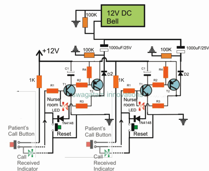
Referring to the above shown hospital room call bell circuit, the idea may be understood as follows:
The transistor T1, T2 basically forms a transistorized latch circuit wherein a trigger at the base of T1 causes the circuit to hold into a latching mode, meaning a single momentary positive pulse at the base of T1 enables T1/T2 to go into a permanent conduction mode until the feed from R3 is grounded by pressing the reset button.
On pressing the button at the patent's end latches the circuit into conduction and causes a DC pulse to be sent through D2 to the connected DC bell.
The bell sounds loudly until the 1000uF capacitor is charged fully, after which the bell ceases to operate.
However the latching action keeps the RED LED switched ON along with the green LED which is supposed to be positioned in the patient's room beside the call button. This LED informs the patient regarding the call been sent and confirms regarding the same. The red LED intimates the nurse regarding the patient's room.
Identical stages as explained above may be repeated and installed for each of the rooms in the hospital for enabling the respective occupants to execute a foolproof interaction with the nurses rooms whenever the patient may be in need for help.
The reset button is provided for enabling the nurse to reset or restore the situation back to the switched OFF condition which also simultaneously tells the patient regarding the response from the nurse's room, so that the patient is able to anticipate the help being on the way.
Parts List for the proposed hospital call circuit
R1 = 100K
R2, R3, R4 = 4K7
C1 = 100uF/25V
D2 = 1N4007
T1 = BC547
T2 = TIP127
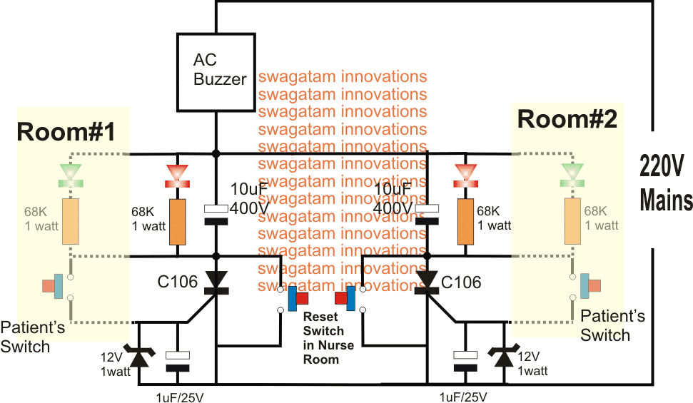
Hospital Room Call Bell Circuit using SCR


Comments
can i be able to simulate in my proteus8?
Sure, you can do it.
Does anybody know if a Pcb is available for the Hospital single room call bell circuit
Sorry, PCB is not available for this project
I will like to use this for my undergraduate project, can you help me with details of the software and the design principles?
There’s no software used in this circuit, only electronic parts.
For my projet I was asked to do a simulation and debugging for the hospital room call bel please can you give me some advice and how to represent it on my paper?
Hello, I am a university research student please for this type of hospital alarm how will the circuit altered if the following requirements are to be done
1. An indicator shows the corresponding location of the room.
2. Only one nurse room controlling 10 patient rooms.
Hello, both the features are already present in the first design.The RED LEDs indicate the corresponding room numbers, or from which room the button was pressed. All the RED LEDs are supposed to be installed inside a single control room.
Thank you for your reply, I have some other questions.
How can the circuit be adapted for a 10 hospital room center?
How can we modify the circuit to have an alternate power source in case of power shortage?
You only have to repeat the stages 10 times for getting 10 room facility. For back up you will need to add a battery system to the circuit.
Hi I am siva
Resistor value 1/4 ,1/2,1w or 2w
Hi Siva, when not specified it is always 1/4 watt, that’s the standard rule…
hi I made the simulation of the circuit and finally its working just fine I even included a 555 timer circuit and a buzzer to make it pulse width continuously, but what I notice with my simulation is that 100uf is feeding the collector of my t1 and so even prior to ON the pshbutton1(patient button) the leds will stay ON so I decided to finally remove the capacitor and it works just fine without any false triggering. my question is, is there any problem for removing the 100uF(considering the first circuit with 12VDC).
Hi, that is why I never use simulators, how can 100uF trigger anything in the circuit? it is blocked by T1 and T2? that’s rubbish result from the simulator. 100uf is strictly required so that T1 does not get triggered by spurious stray external signals.
I would advise you to build it practically which will help you to get correct results and you will be able to learn electronics correctly
Hello Swagatam
I love the circuit , and I am ready to test and build it , few question though
1. Can I make the button wireless to increase the range
2. Is it possible to add a receiver display that will be carried along by the nurse which will indicate the button pressed
3.can I increase button per patient , different assistance , maybe two button per patient and reporting to the nurse differently as per function
I need to convert the same diagram to Supermarket Supervisor Teller Assistance ,
Please help
Thanks
Thanks Lufono,
1) For a wireless operation you will require a Tx/Rx pair on both sides for each button.
2) for each button you may have to include a separate latch circuit, and for a wireless a more complex circuitry might be required in order to send separate unique signals to the Rx side from each patient.
So a wireless set up could be extremely costly.
Hi.. i m amol i use all that component and make a circuit but they are false triggering and circuit will not done work properly pls help me in hospital room call bell system
Hi, The design is a simple transistor latch and will definitely work if implemented correctly.
do not make the whole circuit together, fist make and test a single T1/T2 stage and check the response by pressing the relevant buttons.
you can connect a 1uF capacitor across base/emitter of T1 to make sure that the T1 does not get disturbed due to long wires connected with base resistor.
please first understand the working and then make it.
Hi..first one circuit i had use all proper component but still that not work and led will running countinus and not done ..will you pls help me
Hi, which circuit did you make, the first one, or the last one using SCR?