• Skip to main content
  • Skip to primary sidebar

Homemade Circuit Projects

Need circuit help? Post them in the comments! I've answered over 50,000!

Blog | Categories | About | Contact | Calculators-online
You are here: Home / Security and Alarm / Office Call Bell Network Circuit with LED Monitor

Office Call Bell Network Circuit with LED Monitor

Last Updated on November 15, 2023 by Swagatam 2 Comments

In this post I have explained an office call bell network circuit for office complexes which could be used for calling and monitoring office member's attendance and response from the particular intended office chamber. The idea was requested by Mr. Rajib Banerjee

Table of Contents
  • Technical Specifications
  • The Design
  • Circuit Diagram
  • How it Works
  • The Relay Driver Circuit
  • Parts list

Technical Specifications

Need a perfect useable circuit idea for Ringing the Bell as different Department of the office from single point.

Say, 20 department calling system from a central office.

When push the switch for 'x' department then an existing electrical calling bell is ringing till anyone from that department come to attending to the central office and it's time taking to attend because of distance to each other.

Now need a circuit which work like when calling the Bell from Central office to any dept, the attendant who attend the central office just push switch from that dept. for the signal that he/she is hearing the bell and just coming.

After pushing the switch from Dept a light glow besides the calling switch of Central office. just this which i can incorporate with the existing using one way calling system and give me the alteration as diagram.

The Design

The proposed office call bell circuit as requested above may be summarized as follows:

The central head office needs to be connected to each of the office departments such that pressing the respective push  buttons rings the corresponding bell in the desired office chamber.

In an event the concerned office member is not in the "called" office, but in some other nearby department and hears the ringing, is able to respond by attending the "answer button" from the other office the member may be situated during that instant.

The above response gets stored in the form a glowing LED in the head office allowing the attendant there to check the concerned members exact position.

The circuit implementation of the proposed office call bell monitor network can be done by using a group of set/reset flipflops as may be witnessed in the following diagram:

Circuit Diagram

Office Call Bell Network Circuit with LED Monitor

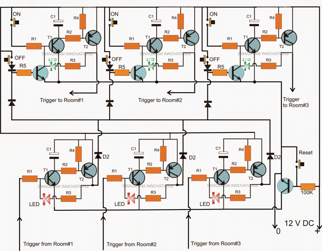
The circuit above illustrates an example wiring for three office rooms which may be extended to any desired numbers simply replicating the stages.

How it Works

As can be seen the upper section comprises three identical stages of transistor set/reset modules, each module being made up of two NPN transistors, one PNP, a couple push buttons and a few resistors.

The push button marked as "ON" is used for activating or triggering the latch circuit made up of T1 and T2. The OFF button does the opposite that is deactivates the particular module activation.

When activated a positive voltage becomes available at the collector the corresponding PNP transistor which is terminated for triggering the office bell situated at the particular office, in the diagram these are labelled as "Trigger to room#1, room#2, room#3...."

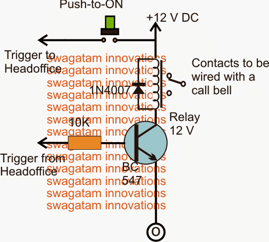
When one of these triggers is activated it's conveyed to a relay driver circuit system installed in the intended office chamber where the trigger is fed to the base of the relay driver transistor as shown in the diagram below (labelled as "trigger from head office").

This prompts the relay to get activated and also the connected bell across the relay contacts.

The member now presses the green switch in response which is conveyed back to the head office and collected across one of the inputs marked "trigger from room#1, room#2 room#3..." depending upon from where the member may have attended the green button. This action enables an instant switching off of the bell.

If it was from the concerned room, say for example room#1 then the corresponding red LED positioned in "room#1"module gets illuminated and latched, if it was from any other room the corresponding red LED is illuminated providing the correct instantaneous location of the member during his/her response to the call made from the head office.

The red LED illumination may be reset and restored to its switched OFF position by pressing the reset button at the extreme right corner of the above head office call bell monitor circuit above.

The Relay Driver Circuit

bell relay driver circuit

Parts list

All R1 = 100 k
All R2, R3, R4 = 10 K
All diodes = 1N4148
All C1 = 100uF/25V
All NPN = BC547
All PNP = BC557

You'll also like:

  • 1.  Power Interruption Alarm Circuit for Instant Power Failure Indications
  • 2.  Battery Low Voltage Alarm Circuit
  • 3.  RFID Security Lock Circuit – Full Program Code and Testing Details
  • 4.  DIY Taser Gun Circuit – Stun Gun Circuit
  • 5.  Touch Alarm Circuit
  • 6.  Wireless Home Security Circuit – Solar Powered

About Swagatam

I am an electronics engineer with over 15 years of hands-on experience. I am passionate about inventing, designing electronic circuits and PCBs, and helping hobbyists bring their projects to life. That is why I founded homemade-circuits.com, a website where I share innovative circuit ideas and tutorials. Have a circuit related question? Leave a comment.... I guarantee a reply!

Previous Post: « Sine Wave Inverter using Bubba Oscillator Circuit
Next Post: Solar Powered Induction Heater Circuit »

Reader Interactions

Comments

  1. Abu-Hafss says

    November 15, 2014 at 6:38 pm

    Nice job!

    Reply
    • Swagatam says

      November 16, 2014 at 10:47 am

      thank you Abu-Hafss.

      Reply

Need Help? Please Leave a Comment! We value your input—Kindly keep it relevant to the above topic! Cancel reply

Your email address will not be published. Required fields are marked *

Primary Sidebar

Subscribe to New Circuit Ideas

Categories

  • Arduino Projects (87)
  • Audio and Amplifier Projects (132)
  • Automation Projects (17)
  • Automobile Electronics (101)
  • Battery Charger Circuits (83)
  • Datasheets and Components (104)
  • Electronics Theory (143)
  • Free Energy (37)
  • Games and Sports Projects (11)
  • Grid and 3-Phase (19)
  • Health related Projects (25)
  • Home Electrical Circuits (12)
  • Indicator Circuits (14)
  • Inverter Circuits (87)
  • Lamps and Lights (142)
  • Meters and Testers (69)
  • Mini Projects (46)
  • Motor Controller (64)
  • Oscillator Circuits (27)
  • Pets and Pests (15)
  • Power Supply Circuits (108)
  • Remote Control Circuits (50)
  • Security and Alarm (64)
  • Sensors and Detectors (101)
  • Solar Controller Circuits (59)
  • Temperature Controllers (42)
  • Timer and Delay Relay (49)
  • Transmitter Circuits (29)
  • Voltage Control and Protection (37)
  • Water Controller (36)

Calculators

  • Battery Back up Time Calculator
  • Capacitance Reactance Calculator
  • IC 555 Astable Calculator
  • IC 555 Monostable Calculator
  • Inductance Calculator
  • LC Resonance Calculator
  • LM317, LM338, LM396 Calculator
  • Ohm’s Law Calculator
  • Phase Angle Phase Shift Calculator
  • Power Factor (PF) Calculator
  • Reactance Calculator
  • Transistor Astable Calculator
  • Transistor base Resistor Calculator
  • Voltage Divider Calculator
  • Wire Current Calculator
  • Zener Diode Calculator
  • Filter Capacitor Calculator
  • Buck Converter Calculator
  • Boost Converter Calculator
  • Solar Panel, Inverter, Battery Calculator
  • Wire Current Calculator
  • SMPS Transformer Calculator
  • IC SG3525, SG3524 Calculator
  • Inverter LC Filter Calculator

People Also Search

555 Circuits | 741 Circuits | LM324 Circuits | LM338 Circuits | 4017 Circuits | Ultrasonic Projects | SMPS Projects | Christmas Projects | MOSFETs | Radio Circuits | Laser Circuits | PIR Projects |

Recent Comments

  • Swagatam on Understanding SG3525 IC Pinouts
  • Dan on Understanding SG3525 IC Pinouts
  • Swagatam on High Current Wireless Battery Charger Circuit
  • Swagatam on Timer Based Cell Phone Charger Circuit
  • Nitesh Agrawal on Timer Based Cell Phone Charger Circuit

Company

  • Privacy Policy
  • Cookie Policy
  • About Me
  • Contact
  • Disclaimer
  • Copyright
  • Videos
  • Sitemap

Social Profiles

  • Twitter
  • YouTube
  • Instagram
  • Pinterest
  • My Facebook-Page
  • Quora
  • Stack Exchange
  • Linkedin
  • © 2025 · Swagatam Innovations