In this post I have explained a simple automatic High Voltage Battery Charger Circuit which can be used for an automatic charging control of any preferred high voltage battery bank such as a 360V battery bank. The idea was requested by "resonance".
Circuit Objectives and Requirements
- I found all your circuit and projects interesting but please I need a special assistance.
- I want to build a Low and high battery full cutoff that can handle about 360VDC (30 Batteries in series) such that when battery is full at 405VDC charging Voltage will cutoff and when battery drop to like 325VDC it also cutoff battery low.
- Please, do share this experience with me.
Circuit Diagram
The Design
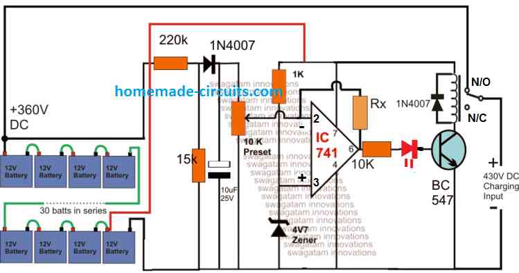
The figure above shows a straightforward configuration for achieving the proposed automatic high voltage battery charger circuit in the order of 360V.
The idea is based on the standard opamp based comparator principle, which is also implemented in many of the earlier 741 based battery charger circuits.
The circuit functionality can be understood as I have explained below:
The 360V is achieved by adding 30 nos of 12V batteries in series, which constitutes 430V level as the full charge threshold, and 330V as the full discharge level threshold.
The battery bank voltage needs to be controlled within these limits for ensuring a safe charging environment for the batteries.
The opamp circuit is configured for implementing the above mentioned high voltage charging control as indicated in the diagram.
The 360 V is stepped down to a suitable proportional level for the opamp sensing input at its inverting pin#2 applied via a 10 k preset. This is done through a potential divider network using a 220 k and a 15 k resistor.
The non-inverting pinout of the opamp is clamped at 4.7 V through a zener diode for providing a reference to its complementing pin#3 sensing input.
The operating supply voltage for the opamp pin#7 is extracted from one of the batteries associated with the negative line of the system.
Preset Adjustment
The preset is adjusted such that the opamp output pin#6 just becomes high and triggers the transistor when the battery voltage reaches at around 430V.
The above action forces the relay to operate and cuts off the supply charging voltage to the battery bank.
As soon as this happens, the battery voltage tends to go down a bit which normally prompts the opamp to trigger back the relay ON, however the presence of the feed back resistor connected across pin#6 and pin#3 holds the opamp situation, and prevents this from happening.
This is also called the hysteresis resistor which temporarily latches the opamp to a certain voltage range depending on the value of this resistor (Rx).
Here it must be selected such that the opamp stays latched until the voltage of the battery bank drops to about 330V, after which the opamp could be expected to restore the relay back in its N/C position initiating the charging process for the batteries.


Comments
sir i have 16v,4amp charger and 15.80v lithium battery can i use this circuit to set my full charge cutoff???
Hi Bashir, you can use it by suitably removing the resistive divider stage shown at the left side of the diagram
sir if i want to use above circuits to charge a 178volt 1200amps lithium pack what are the changes that need to be made to the circuit
The charging amps for the pack is 100amps through a 5kva transformer and 100amp bridge with alternator diodes
Abioye, you can use this circuit to charge your battery, but you will have to change the relay with a 150 amp relay, and to control this relay you will need to replace the shown transistor with a TIP 122 transistor, the base zener can be replaced with an LED for indicating the charging and shut off operations
hi swagatam
i love your site, so let me explain about my problem at my final project to pass the university.
can i charge the battery lipo with feature cc and cv and controlled by arduino? my battery is 16.8 volt when full charge and 5200mAh. so i want charge it with cc at max 1C but adjustable with arduino and fix 4.2 volt. my battery have 4 cells, which each cell is 4.2volt when full charge. please help me. this is my final project to pass. PLEASE :(((
regard
Thanks Tesla,
CC and CV is recommended for all types of batteries so it's fine for Lipo also.
For me it could be difficult to get it done using an Arduino, still I'll try and see if it's possible or not and let you know.
Hi Swagatam
I have really enjoyed this site and the various circuits. This will be my first circuit build so I need basic help with this please.
I am wanting to charge large battery bank and want to use this circuit.
I will have access to 12 volts form this bank.
Charger max 10 amps at 120 volts
My question's are what/how is value/formula for the hysteresis (Rx) and what
part number/type of relay.
thanks Wayne
relay can be any 400 ohm, 12V SPDT type
Thanks Wayne,
the formula you are expecting can be learned from this article:
http://www.ti.com/lit/ug/tidu020a/tidu020a.pdf
the easiest way is to do it by using a variable resistor for Rx….and then vary this resistor until the lower cut off point is achieved or identified, once identified then this point of the variable resistor or the preset could be sealed.
Hi Swagatam
I am wanting to charge large battery bank and want to use this circuit.
My question's are what/how is value/formula for the Hysisterious (Rx) and what part number/type of relay.
thanks Wayne
Thanks for the feed back.
I apologize for the double post wasn't sure I post the first time.
would that be 10k pot?
Thanks Wayne
Hi WCH63,
I'll have to figure it out with some thinking, however the easiest possible method is to find it out practically by using a pot across the feedback link, and then adjust this pot until the lower break point is identified