In this article I have explained how to make a simple fish aquarium oxygen generator circuit using the concept of electrolysis of water.
Generating Pure Oxygen
The production of oxygen through electrolysis can be expected to supply a pure and a bigger quantity of oxygen compared to the usual pumped air concept which injects only only a portion of oxygen in the aquarium, therefore using electrolysis procedure looks a more efficient than the pumped air option
In one of my earlier artilces I have explained how to generate oxygen and hydrogen gas through electrolysis in large volumes, here we employ the same principle for the generation of pure oxygen using mains rectified AC.
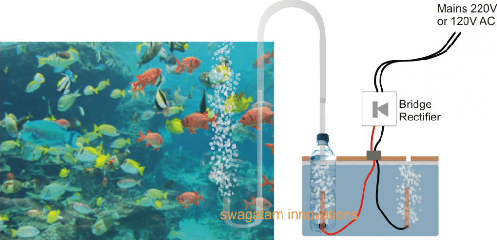
The complete operational set up can be witnessed in the above shown figure.
The right side section of the diagram shows a small tank filled with clean tap water, having a lid which is appropriately fabricated to hold a plastic bottle such that its neck can protrudes out, and having a small opening some distance away for allowing the unused hydrogen gas to escape.
Two wires can be seen entering the water container with one of the wires pushed inside the bottle from its bottom end and appropriately sealed with epoxy glue and the other wire loosely held just below the lid opening.
The wire entering the bottle end is tied up with an electrode which could be ideally of graphite (salvaged from an old dead AAA cells) in order to prevent degradation due to oxidization, overtime
The wires can be seen attached with the output of a bridge rectifier, which is supplied with an input from the mains AC 220V or a 120V.
When mains is switched ON, the power enters the bridge rectifier and gets converted into a pulsating DC, this DC is introduced inside the water tank for initiating the required electrolysis.
The potential at positive end electrode of the wire generates O, or pure oxygen, while the potential at the negative wire electrode breaks H+H atoms from water generating hydrogen which escapes through the lid opening into the atmosphere.
The oxygen gas is forced to bubble inside the water enclosed inside the bottle and it emanates through the tube into the aquarium where it bubbles back from bottom to the surface enriching the water with pure oxygen and making sure that the marine life inside the aquarium gets the best of the experience in terms of breathing and oxygen absorption.
Please note that in the discussed concept the water alone is forced to break into its constituent parts, absolutely NO external catalyst in the form acid or salt should be added in the electrolysis tank, which might otherwise cause the generation of poisonous gasses instead of oxygen.
Making the Bottle Oxygen Collector
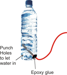
The bottle which acts as the intermediate oxygen collector can be easily built using any ordinary empty cold drink bottle or a mineral water bottle.
As demonstrated in the figure below, the wire end with the electrode is inserted from the bottom corner of the bottle and sealed with epoxy glue or putty.
Next, many small holes are punched near the bottom end of the bottle so that water is able to enter and fill the bottle and enable the process of electrolysis inside it.
Further on, a plastic flexible tube is inserted through the lid or the cork of the bottle and glued with epoxy, the other end of the tube is immersed in the aquarium jar for allowing the oxygen to pass into it for initiating the required fish aquarium oxygen generation.
After this the bottle is pushed in the tank so that water fills in and hlds the bottle erect in the tank. The wires are then appropriately attached with the bridge rectifier source enclosed inside a plastic box, with a mains cord terminating out from the input of the bridge.
That's it! Once the above procedures are finished, it's just about plugging and switching ON the mains, and watching the the oxygen bubbling out inside the fish aquarium, making the lives of the fishes merrier.
Warning: The explained electrolysis set up for the fish aquarium generator circuit is very dangerous due to the involvement of AC mains in the electrolysis tank. Extreme caution and safety must be exercised while building and testing the proposed units.


Comments
Sir Can You Provide Me A Simple Buzzer Circuit. when Get Power It Will Beep 10 second thn Get off . When The Power Come Again Thn Start For 10 second.
i want to use It For My DC IPS. when Main Power 12 Volt Get This Circuit It will Beep the Buzzer thn stoped For This Season. when the power Source Off The Circuit will Reset. and when the Power Come again then the Circuit Will Work.
Sir Can You Please Provide Me 3V Relay Module Circuit. Please Sir
you can refer this article:
https://www.homemade-circuits.com/2012/01/how-to-make-relay-driver-stage-in.html