• Skip to main content
  • Skip to primary sidebar

Homemade Circuit Projects

Need circuit help? Post them in the comments! I've answered over 50,000!

Blog | Categories | About | Contact | Calculators-online
You are here: Home / Voltage Control and Protection / Do We Need a Freewheeling Diode Across the Inductor in Boost Converter?

Do We Need a Freewheeling Diode Across the Inductor in Boost Converter?

Last Updated on May 11, 2025 by Swagatam Leave a Comment

So here we are trying to understand whether we must put a freewheeling diode directly across the inductor in a boost converter or not, to safeguard the switching transistor?

Table of Contents
  • How Boost Converter Works
  • What Happens if We Add Diode Across Inductor?
  • What About No Load Condition?
  • No Load Can Still Be Risky in Some Cases
  • Conclusion

How Boost Converter Works

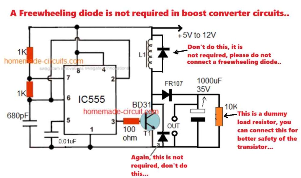
So in a boost converter, we got one inductor, one power switch like a MOSFET, one diode and one output capacitor. Input is from DC source like 12V.

When MOSFET switches ON then current from the DC source flows through inductor and charges it, energy goes inside inductor in magnetic form. During this time, diode is reverse biased so it does not conduct, load gets power from output capacitor.

Then, when MOSFET switches OFF, the inductor wants to keep current flowing and since MOSFET is OFF now, the diode becomes forward biased and all that energy from inductor pushes ahead through the diode and charges the output capacitor and powers the load. This is how voltage gets boosted.

freewheeling diode in boost converter

What Happens if We Add Diode Across Inductor?

Now suppose we add one freewheeling diode across the inductor directly. That means the diode cathode goes to one side of inductor and anode to other side.

When MOSFET turns OFF then this diode will try to conduct and give inductor an alternate path. So now instead of pushing current to output, the inductor will dump energy back to itself via this diode loop, and whole boost effect is gone. So output never gets boosted.

That diode becomes a short cut path and kills the boost action.

What About No Load Condition?

Now some may ask what happens if there is no load at output? Like when nobody is drawing current. Will inductor flyback cause damage to the transistor?

Answer is no, because the inductor already has a proper flyback path through the output diode and capacitor. Even if load is zero, energy still goes to output capacitor.

Voltage might increase slightly if output cap is small but no harm to components. If you are too worried then just add some dummy load like a resistor at output to soak some charge.

No Load Can Still Be Risky in Some Cases

So when we say "risky without load," it does not mean the boost converter will immediately blow up. What we mean is — under no-load condition if the output capacitor is too small or the feedback loop is not smart then yes, voltage can keep rising and rising with each switching cycle because nobody is there to consume that extra energy. This can push the output voltage above safe limits.

But… that does not mean you need to put a freewheeling diode across the inductor. That would totally ruin the boost process like we discussed. The solution is not diode, but to:

Make sure you have a decently rated output capacitor (big enough to absorb temporary excess energy).

Use a minimum dummy load resistor if your circuit allows, just to drain some charge if nothing else is consuming.

Most importantly, have a proper feedback system (PWM control) that senses output voltage and stops boosting once target is reached.

So yeah — it is not dangerous because of inductor not having flyback path (that is already handled by output diode), it is dangerous if you have bad control or no feedback in no-load cases.

Conclusion

So in short, never put any freewheeling diode directly across the inductor in a boost converter. It will kill the boost process. That diode is not needed. Instead, always make sure output diode and capacitor are there and properly connected, along with a small dummy load. That is all we need for safe operation.

You'll also like:

  • 1.  Using an NTC Thermistor as a Surge Suppressor
  • 2.  How RCCB Works [with Circuit Diagram]
  • 3.  SCR/Triac Controlled Automatic Voltage Stabilizer Circuit
  • 4.  How to Test a MOV (Metal Oxide Varistor) Surge Protector Device
  • 5.  Adjustable Voltage Regulator Circuit using LM324 IC with Over Current Protection
  • 6.  Automatic Voltage Stabilizer Circuit for TV sets and Refrigerator

About Swagatam

I am an electronics engineer with over 15 years of hands-on experience. I am passionate about inventing, designing electronic circuits and PCBs, and helping hobbyists bring their projects to life. That is why I founded homemade-circuits.com, a website where I share innovative circuit ideas and tutorials. Have a circuit related question? Leave a comment.... I guarantee a reply!

Previous Post: « How Load Conducts in Half-Bridge Driver Circuits like IR2184 or IR2110
Next Post: Real MPPT Solar Charger Circuit Using Arduino, LCD, and Manual/Auto Switch »

Reader Interactions

Need Help? Please Leave a Comment! We value your input—Kindly keep it relevant to the above topic! Cancel reply

Your email address will not be published. Required fields are marked *

Primary Sidebar

Subscribe to New Circuit Ideas

Categories

  • Arduino Projects (87)
  • Audio and Amplifier Projects (132)
  • Automation Projects (17)
  • Automobile Electronics (101)
  • Battery Charger Circuits (83)
  • Datasheets and Components (104)
  • Electronics Theory (143)
  • Free Energy (37)
  • Games and Sports Projects (11)
  • Grid and 3-Phase (19)
  • Health related Projects (25)
  • Home Electrical Circuits (12)
  • Indicator Circuits (14)
  • Inverter Circuits (87)
  • Lamps and Lights (142)
  • Meters and Testers (69)
  • Mini Projects (46)
  • Motor Controller (64)
  • Oscillator Circuits (27)
  • Pets and Pests (15)
  • Power Supply Circuits (108)
  • Remote Control Circuits (50)
  • Security and Alarm (64)
  • Sensors and Detectors (101)
  • Solar Controller Circuits (59)
  • Temperature Controllers (42)
  • Timer and Delay Relay (49)
  • Transmitter Circuits (29)
  • Voltage Control and Protection (37)
  • Water Controller (36)

Calculators

  • Battery Back up Time Calculator
  • Capacitance Reactance Calculator
  • IC 555 Astable Calculator
  • IC 555 Monostable Calculator
  • Inductance Calculator
  • LC Resonance Calculator
  • LM317, LM338, LM396 Calculator
  • Ohm’s Law Calculator
  • Phase Angle Phase Shift Calculator
  • Power Factor (PF) Calculator
  • Reactance Calculator
  • Transistor Astable Calculator
  • Transistor base Resistor Calculator
  • Voltage Divider Calculator
  • Wire Current Calculator
  • Zener Diode Calculator
  • Filter Capacitor Calculator
  • Buck Converter Calculator
  • Boost Converter Calculator
  • Solar Panel, Inverter, Battery Calculator
  • Wire Current Calculator
  • SMPS Transformer Calculator
  • IC SG3525, SG3524 Calculator
  • Inverter LC Filter Calculator

People Also Search

555 Circuits | 741 Circuits | LM324 Circuits | LM338 Circuits | 4017 Circuits | Ultrasonic Projects | SMPS Projects | Christmas Projects | MOSFETs | Radio Circuits | Laser Circuits | PIR Projects |

Recent Comments

  • Swagatam on Battery Deep Discharge Protection Circuit
  • Swagatam on 10 LED Tachometer Circuit Diagram
  • Drew Adare on How to Collect Free Energy from Atmosphere
  • Göran on 10 LED Tachometer Circuit Diagram
  • Abdulmajid Haruna on Laptop Power Bank Circuit

Company

  • Privacy Policy
  • Cookie Policy
  • About Me
  • Contact
  • Disclaimer
  • Copyright
  • Videos
  • Sitemap

Social Profiles

  • Twitter
  • YouTube
  • Instagram
  • Pinterest
  • My Facebook-Page
  • Quora
  • Stack Exchange
  • Linkedin
  • © 2025 · Swagatam Innovations