• Skip to main content
  • Skip to primary sidebar

Homemade Circuit Projects

Need circuit help? Post them in the comments! I've answered over 50,000!

Blog | Categories | About | Contact | Calculators-online
You are here: Home / Archives for Oscillator Circuits

Oscillator Circuits

IC 4047 Astable, Monostable Oscillator Circuits

Last Updated on November 4, 2025 by Swagatam 5 Comments

4047 complement gating astable circuit compressed

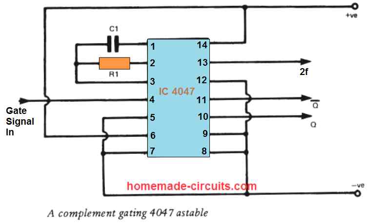
In an IC 4047 astable oscillator circuit, the output of the IC continuously generates a switching ON/OFF signal. Since the output is never in a stable state and constantly switches between and low and high, it is called an astable multivibrator. The astable ON/OFF switching frequency is adjustable and can be varied by changing the […]

Filed Under: Oscillator Circuits Tagged With: 4047, Astable, Circuits, Monostable

Understanding CMOS IC 4035 Datasheet – 4-Bit Parallel In Parallel Out Shift Register

Last Updated on June 24, 2025 by Swagatam 2 Comments

So now we are talking about this digital IC called 4035 which is made using CMOS technology, that means it will use very low current and will give us high noise immunity. Inside this IC we have got 4 flip-flops which are arranged in such a way that they can hold and shift 4-bit data. […]

Filed Under: Datasheets and Components, Oscillator Circuits Tagged With: 4035, CMOS, Datasheet, Parallel, Shift, Understanding

2 Simple Voltage to Frequency Converter Circuits Explained

Last Updated on January 19, 2025 by Swagatam 7 Comments

C2

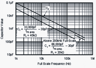
A voltage to frequency converter circuit converts a proportionately varying input voltage int a proportionately varying output frequency. The first design is using the IC VFC32 which is an advanced voltage to frequency converter device from BURR-BROWN specifically designed to produce an extremely proportional frequency response to the fed input voltage for a given voltage […]

Filed Under: Oscillator Circuits Tagged With: Circuits, Converter, Explained, Frequency, Simple, Voltage

10 Simple Unijunction Transistor (UJT) Circuit Diagrams Explained

Last Updated on January 17, 2025 by Swagatam 21 Comments

UJT Pulse Generator

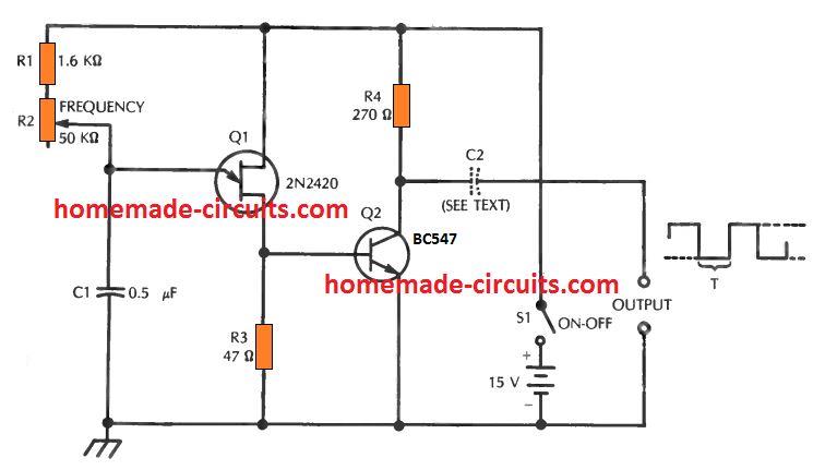
In the earlier post I have explained comprehensively about how a unijunction transistor works, in this post I will elucidate a few interesting application circuits using this amazing device called UJT. The example application circuits using UJT which are explained in the article are: 1) Square Wave Pulse Generator The first design below demonstrates a […]

Filed Under: Oscillator Circuits Tagged With: Diagrams, Explained, Simple, Transistor, UJT, Unijunction

10 Easy Op-amp Oscillator Circuit Diagrams Explained

Last Updated on January 17, 2025 by Swagatam 5 Comments

formula for calculating C1 and L1

In an op amp oscillator circuit, an op amp is configured with a resistor-capacitor feedback loop or a inductor-capacitor feedback loop, which triggers the op amp to go into an oscillating mode, generating a switching ON/OFF pulses from its output pin. The high-gain and wide passband of operational amplifier (op amp) ICs makes it possible […]

Filed Under: Oscillator Circuits Tagged With: Diagrams, Easy, Explained, Oscillator

1 Hz to 1 MHz Frequency Reference Generator Circuit Diagram

Last Updated on January 17, 2025 by Swagatam 36 Comments

1 MHz time base

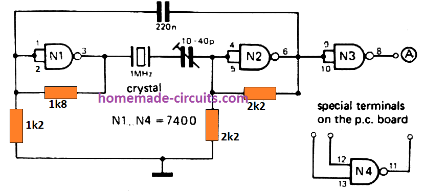
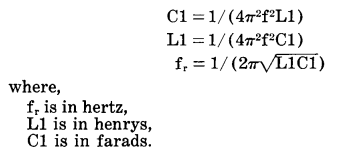
This circuit is an universal frequency generator which you can use in numerous frequency and time period testing applications. It is primarily well suited for a gate pulse generator in frequency counters. The circuit is capable of generating an entire range of reference frequencies such as 1 Hz, 5 Hz, 10 Hz, 50 Hz, 100 […]

Filed Under: Oscillator Circuits Tagged With: Frequency, Generator, Reference

  • Page 1
  • Page 2
  • Page 3
  • Interim pages omitted …
  • Page 5
  • Go to Next Page »

Primary Sidebar

circuit simulator image


Subscribe to get New Circuits in your Email


Categories

  • Arduino Projects (93)
  • Audio and Amplifier Projects (133)
  • Automation Projects (17)
  • Automobile Electronics (101)
  • Battery Charger Circuits (85)
  • Datasheets and Components (109)
  • Electronics Theory (149)
  • Energy from Magnets (27)
  • Games and Sports Projects (11)
  • Grid and 3-Phase (20)
  • Health related Projects (27)
  • Home Electrical Circuits (13)
  • Indicator Circuits (16)
  • Inverter Circuits (95)
  • Lamps and Lights (159)
  • Meters and Testers (71)
  • Mini Projects (28)
  • Motor Controller (68)
  • Oscillator Circuits (28)
  • Pets and Pests (15)
  • Power Supply Circuits (91)
  • Remote Control Circuits (50)
  • Renewable Energy (12)
  • Security and Alarm (64)
  • Sensors and Detectors (106)
  • SMPS and Converters (34)
  • Solar Controller Circuits (60)
  • Temperature Controllers (43)
  • Timer and Delay Relay (49)
  • Voltage Control and Protection (42)
  • Water Controller (36)
  • Wireless Circuits (30)


Other Links

  • Privacy Policy
  • Cookie Policy
  • Disclaimer
  • Copyright
  • Videos
  • Sitemap


People also Search

555 Circuits | 741 Circuits | LM324 Circuits | LM338 Circuits | 4017 Circuits | Ultrasonic Projects | SMPS Projects | Christmas Projects | MOSFETs | Radio Circuits | Laser Circuits | PIR Projects |

Social Profiles

  • Twitter
  • YouTube
  • Instagram
  • Pinterest
  • My Facebook-Page
  • Stack Exchange
  • Linkedin


Recent Comments

  • Swagatam on Arduino 2-Step Programmable Timer Circuit
  • Swagatam on Automatic Street Light Dimmer Circuit
  • Ghulam Mohio Din on Automatic Street Light Dimmer Circuit
  • Swagatam on Motorcycle Voltage Regulator Circuits
  • Swagatam on 5 Simple DC Motor Speed Controller Circuits Explained

© 2026 · Swagatam Innovations