These useful lightweight, cheap, analogue tachometer circuits are developed for facilitating car or auto servicing mechanics for precisely adjusting a car ignition system RPM to get maximum efficiency from it. The proposed circuits are actually combined results of a tachometer and a dwell meter.
Application
The car RPM servicing meter circuit can be applied for analyzing the ignition timing at several RPMs, along with a timing lamp. When the circuit is utilized in the form of a dwell meter it can be used for reading the angle at which the ignition pulse is switched ON, and thus it can provide the necessary information to the auto mechanic regarding the timing adjustment of the CDI circuit.
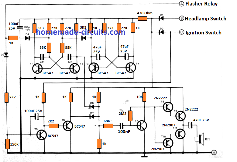
The complete configuration is demonstrated in the figure below and is designed for cars or automobile having negative earthing system, that the majority of contemporary cars have.
The idea can be also tailored for positive earth vehicles by connecting all diodes and electrolytic capacitors with reverse polarity, and by replacing PNP transistors with NPN and vice versa. The circuit is powered through the car battery supply itself. The working of the circuit can be understood with the following points:
How the Circuit Works
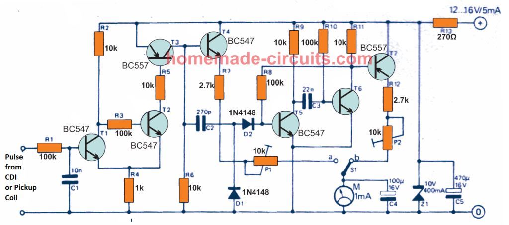
Transistors T1 and T2 are rigged as a Schmitt trigger. For so long as no positive pulse is detected at the input from the pickup coil, T1 stays switched off and T2 is switched on, which means T4 is furthermore switched on. This causes a positive voltage corresponding to the battery supply voltage minus the T4 base-emitter voltage to be generated at T4 emitter.
However, when a positive pulse is generated from the pickup coil, T1 is activated and the Schmitt trigger toggles the opposite way.
T4 is at this point switched off causing voltage existing at its emitter to become zero. The average voltage at the T4 emitter is as a result proportionate to the ratio of ON/OFF switching time of the pickup coil i.e. or in other words, this voltage value is determined by the dwell angle.
When switch S1 is in 'a' position the average current via the meter will also be dependent on the dwell angle, hence the meter could be graduated linearly with respect to the dwell angle.
When the switch is in position 'b' the circuit simply works like a tachometer. C2 works like a differentiator for the pulses coming from T3 collector and the resultant output is used to activate a monostable stage built built around transistors T5 and T6.
The monostable generates constant PWM output, however as the engine RPM increases the duty cycle of the pulses also rises. The average voltage at the T7 emitter, and therefore the average current via the meter, now depends on the ratio of `pulse' to 'no-pulse' period. This means that as the r.p.m. rises and the pulses width get wider, the current via the meter also increases linearly.
How to Calibrate
The device could be calibrated as follows: With S1 in position 'a', connect the R1 input to ground line, then fine-tune P1 to obtain a full scale deflection of the meter. This becomes equivalent to a 360° dwell angle and the scale could be calibrated linearly through 0 to 360 degrees.
The tachometer scale must be calibrated with full-scale so that it corresponds to the highest optimum r.p.m. For the majority of applications 8000 could be just adequate.
If the tool is to be applied on four and six-cylinder engines, in that case either a couple of scales may be needed, or S1 may need to be substituted by a 3 pole switch and P2 need to be replicated to correspond a single scale for various engine ranges. This is because a six cylinder engine generates proportionately a lot more pulses for a specific r.p.m.
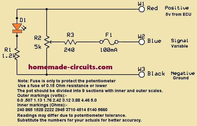
The device could be calibrated with the help of the basic transformer/bridge circuit shown, which produces a 100 Hz waveform.
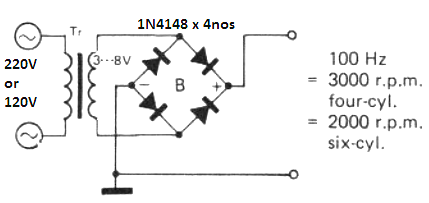
The 100 Hz frequency becomes equivalent to 3000 r.p.m. for a four-cylinder engine, and 2000 r.p.m. for a six-cylinder engine. The output from this circuit is attached to the input of the analogue tachometer device and P2 is tweaked to optimize a precise deflection and reading on the meter.
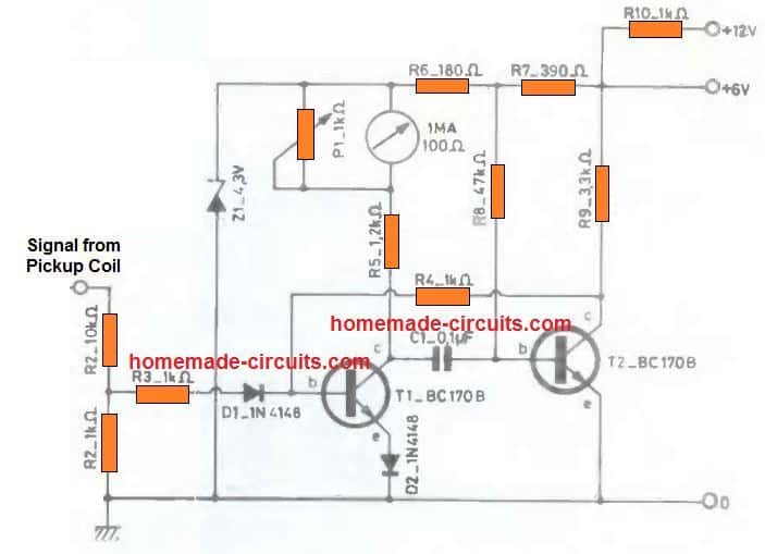
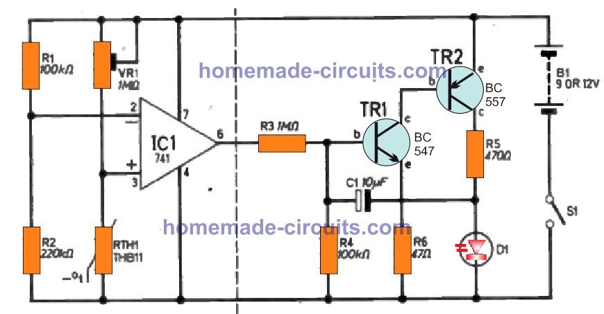
Two Transistor Tachometer for Finding Engine Faults
In the standby position T2 BC107 is in the conducting state. Each time a pulse is generated from the pickup coil, it is applied at the T1, through the resistive divider network R1 and R2.
Resistor R3 is used for limiting the current to the base/emitter junction of T1, while the diode D1 ensures only the positive pulses are allowed to pass and block the bad negative pulses from the pickup coil.
With each pulse from the pickup col, T1 responds causing in a proportionate change in its monostable output effect, which is indicated on the connected meter needle deflection, which is configured as an integrator for the fluctuating monostable signals.
As the engine moves faster, the pickup coil signals also become faster causing the T1, T2 monostable to create longer output siganls for the meter, and meter needle correspondingly deflects higher and higher, and vice versa.
So this simplest tachometer circuit which is built using just a couple of BJTs can be nicely used for understanding the engine performance and for detecting any faults in the engine rotation, by comparing the simple tachometer meter output reading with a normal engine performance.
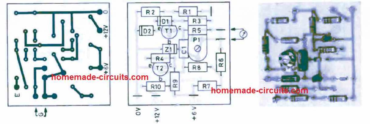
Complete PCB Design Layout
Comments
Your circuits show Pickup from coil . Which terminal ?
Im trying to build a digital tacho for an older 4 Cylinder vehicle. The existing tacho pulse wire is conncted to the + connection on the coil. Reading up , it says the existing system relies on the back emf pulse generated by the contact breaker points opening. Could i adapt your circuit to produce an output.
Every vehicle will have a pick coil for feeding the CDI circuits. Contact breaker is not used nowadays, which are replaced by electronic CDIs. Yes you can adapt my circuit for getting the required output.
In the electrical circuit, the outputs of the transistor T7 are depicted incorrectly.
yes, please invert the emitter/collector pins