The proposed AC mains 220 V load over current cut off circuit continuously monitors the current flowing through a connected load. If this current increases beyond a certain preset level, the circuit trips the relay and disconnects the load from the AC.
Basic Working
This 220 V over current cut off circuit is indeed subject to the relation:
W (Joule) = R (Ohms) x I2 (A) x t (1)
Our setup does not work according to this principle. The detection of an overcurrent relies on a magnetic principle.
To do this, we simply use a small transformer, which we slightly modify from its original purpose by only utilizing the winding with the highest number of turns as the secondary winding.
The primary winding will simply consist of a single turn formed by a wire of sufficient cross-section, wound around the coil passes through the magnetic core and carries the current to be controlled.
Due to the importance of the coil support, we are able to collect (on the secondary side) a sinusoidal waveform whose amplitude is monitored and controlled.
If this amplitude exceeds a given value, the device activates the power relay of the load subject to the protection of the circuit breaker.
Circuit Description
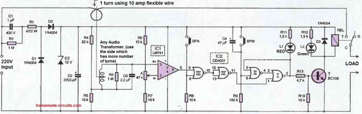
The DC ground necessary for the operation of the setup is provided by the mains through a magnetic coupling.
The capacitor C2 charges during every other half-cycle through the intermediaries C1, R1, and D2. The diode D2 clips the potential at 12V, resulting in a continuous potential of that value.
During the other half-cycles, the capacitor C1 can discharge through R1 via D1, which prepares it to fulfill its purpose during the next active half-cycle.
The resistor R2 allows C1 to discharge when the setup is disconnected from the power grid, preventing an unsuspecting person from experiencing an unpleasant shock by inadvertently touching the terminals of C1.
Overcurrent Detection
The winding characterized by a large number of turns is placed under a DC potential of about 4 to 5V thanks to the voltage divider formed by resistors R4 and R5.
R3 and C3 give the signal a regular sinusoidal shape. On the direct input of the comparator IC1, a sinusoidal potential is observed, whose average value precisely corresponds to the 4 to 5V potential mentioned above.
The inverting input is subjected to an adjustable DC potential, controlled by the slider of the adjustable resistor A.
As long as the peaks of the sinusoid remain below this threshold, the output of IC1 remains in a low state.
However, as soon as this threshold is exceeded, the output switches to a high state during the overruns. This high state is also found on the output of the NOR gate IV of IC2.
Note that it is also possible to trigger a high state on this gate by pressing the push button BPA (stop).
Circuit Breaker Triggering
The NOR gates I and II of IC2 form an R/S flip-flop (Reset/Set). When the circuit is powered on, capacitor C4 charges relatively quickly through R9.
This results in a positive pulse at input 6. The immediate consequence is the transition of the flip-flop's output (pin I) to a high state.
Transistor T saturates, and the utilization relay closes. The controlled load is then powered normally. The green LED L2 is lit, indicating the normal situation.
When an overcurrent occurs, input 1 of flip-flop NOR I experiences a brief high state. The output of the flip-flop immediately transitions to a low state.
Transistor T becomes non-conductive, and the relay opens. The load is no longer powered. The red LED L1 turns on, while the green LED turns off.
Assuming that the load no longer has an overcurrent issue, the BPM (start) button can be pressed to re-engage the circuit breaker.
Diode D3 protects transistor T from the effects of self-induced voltage spikes that mainly occur during relay openings.
Construction
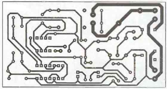
The printed circuit board (PCB) of this setup is depicted in Figure 2 below. Note the wider tracks designed to carry the power current to the protected receiver.
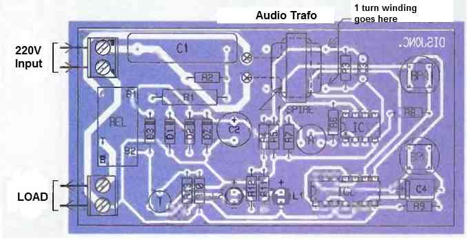
The component layout is indicated in Figure 3. Pay attention to the orientation of the polarized components.
About the Transformer
The transformer used is a small impedance transformer (any audio transformer), and it is necessary to determine the winding with the highest number of turns.
It is sufficient to choose the one with the highest ohmic resistance.
It is especially important to ensure proper insulation between the winding and the inside of the magnetic core by passing the insulating thread.
The sensitivity of the detection increases when turning the adjustable slider counterclockwise. The adjustment can be done experimentally.
How to Setup
By connecting the receiver to be controlled and initially positioning the slider fully clockwise, simply gradually rotate it counterclockwise until the circuit breaker trips. Then, slightly rotate it back in the clockwise direction to achieve an acceptable stability for the circuit breaker.
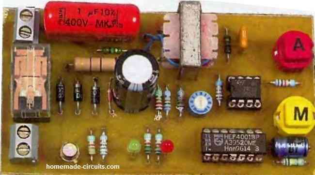
Prototype Image




Discussion & Solutions
Is this circuit for 220v AC?
Swagatam Thanks for posting these circuits. I have a questions or two to ask .
What would be the values needed for C1 and R1 for this circuit to operate at 120vac 60cycles.
Also if you do not mind can you help a old timer ( It’s been over 40 years when I graduated B double E school (Basic electrical electronic school) with the formula for determining the capacitance for calculating cap size for the circuit.
Thank You
Hi Amos,
C1 and R1 values can remain the same for 120 V AC input also. I have explained the capacitor calculations in one of my posts in this blog. You can find the details here:
https://www.homemade-circuits.com/how-to-calculate-and-deduce-current-and/
Thank you for the info and the fast reply.
Thank you Swagatam, I would like to know if R6, R7 and 47K pot are to graduate the desired operation current. They are not mentioned in description. Setup refers to this?
You are right Rafael, The 47K preset and the associated resistors decide at what current the circuit is supposed to trip and switch OFF. Yes the set up refers to this preset.
सर मुझे मोशन सेंसर pcb बनवाने में मेरी मदद करे
Hello Sunil,
Please post this question under a motion sensor article, I will try to help you:
https://www.homemade-circuits.com/ultrasonic-motion-detector-circuit/
Dear Swagatam,
I would like to build a current limiting circuit for a supply of 5VDC with a current limit of 1A . Could you help me?
Hi Alasdair,
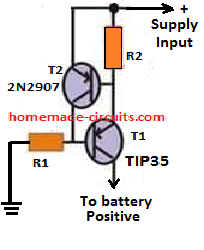
I think you can try the following design to limit the current for your 5V source. The supply input can be the 5V source and the “To battery Positive” can be the output to load:
Thanks for the suggestion Swagatam. I’ll try it out.
You are welcome Alasdair.