In this article we now talk about a very simple but very useful stepper motor controller that uses one A4988 driver module and one 555 astable pulse generator.
Overview Of The Circuit
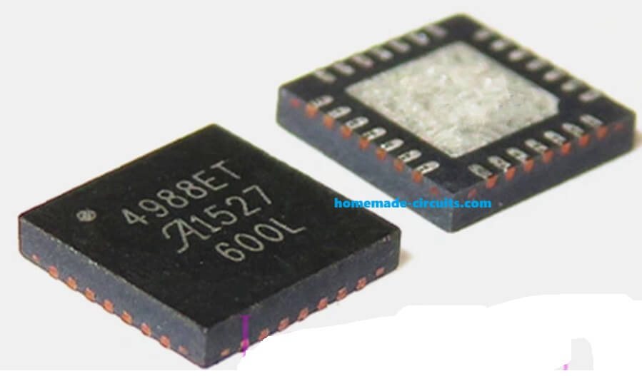
So we first see the main building blocks. We have one A4988 module that drives any small 2 phase stepper motor.
We also have one simple 555 astable oscillator that generates continuous pulses at the STEP pin of the A4988. Higher frequency gives higher rpm. Lower frequency gives lower rpm.
Next we have a 555 monostable circuit used to run the motor for a specific time.
Then we have one SPDT switch for DIR control so that the motor can rotate either clockwise or anticlockwise.
A4988 Full Pinout Explanation
Now we slowly go through every pin of the A4988 driver IC that you see in the attached diagram.

Power And Logic Supply Pins
VDD
This is the logic supply pin. We normally connect +5V here. So this VDD powers the internal logic circuits of A4988.
Since this pin is very sensitive, so we add one 0.22 µF ceramic capacitor close to the pin so that noise is filtered out.
GND
These are the logic grounds. The IC has 2 or 3 GND pins at the bottom, and we connect them all to the main circuit ground. If we do not connect all GND pins then internal reference becomes unstable.
VREG
This pin gives out an internal regulated voltage from A4988. We never load this pin with external devices. We only connect one 0.22 µF capacitor from VREG to GND as shown in the diagram, so that this capacitor stabilizes the internal regulator.
ROSC
This is the internal oscillator pin. In the diagram we see a resistor connected from ROSC to GND.
Usually the recommended value is 47K or 68K depending on the datasheet recommendation, this resistor sets the chopping frequency inside the A4988.
So when we choose a lower resistor value then the chop frequency becomes higher, and when we choose a higher resistor value then chop frequency becomes lower.
Charge Pump Pins
CP1 And CP2
These are the charge pump capacitor pins. In the diagram we see one 0.1 µF capacitor connected between CP1 and CP2.
This capacitor helps the internal high-side MOSFETs to switch properly. So if this capacitor is missing then the motor output may not work correctly.
VCP
This pin also works with the charge pump. We connect one 0.1 µF capacitor between VCP and VBB (motor supply). This gives a boosted voltage that helps the high side drivers to turn on strongly.
Motor Supply Pins
VBB1 And VBB2
These are the motor supply pins.
We connect anywhere from 8V to 35V depending on the stepper motor rating.
Between these two VBB pins and GND we connect one big electrolytic capacitor, usually 100 µF or 220 µF, to suppress voltage spikes.
OUT1A, OUT1B, OUT2A, OUT2B
These are the four outputs that go to the stepper motor coil. We connect coil A to OUT1A and OUT1B. We connect coil B to OUT2A and OUT2B.
Since this is a bipolar motor driver, so all switching is done internally and we do not need external transistors.
Sensing Pins And Sense Resistors
SENSE1 And SENSE2
These pins are for the internal current control system. In the diagram we see low-value resistors, normally 0.1 ohm to 0.2 ohm connected from SENSE pins to ground. These resistors allow the IC to measure the current flowing in coil A and coil B.
So when the current crosses the limit decided by Vref, the IC chops the current automatically.
If we choose:
- Lower value sense resistor → Higher current allowed
- Higher value sense resistor → Lower current allowed
Typical value used is 0.1 ohm.
Control Pins (Logic Interface)
STEP
This is the main step input. Every rising edge makes the motor move one microstep or one full step depending on MS1, MS2, MS3.
In our 555 version, the output of the 555 astable pin 3 goes here.
DIR
This is the direction input. When DIR is HIGH then the motor rotates clockwise. When DIR is LOW then the motor rotates anticlockwise. We use one SPDT switch so that the motor can be reversed manually.
MS1, MS2, MS3
These pins decide the microstepping mode. We can connect them to GND or VDD according to this table:
| Mode | MS1 | MS2 | MS3 |
|---|---|---|---|
| Full Step | 0 | 0 | 0 |
| Half Step | 1 | 0 | 0 |
| Quarter Step | 0 | 1 | 0 |
| Eighth Step | 1 | 1 | 0 |
| Sixteenth Step | 1 | 1 | 1 |
So when we choose higher microstepping then the movement becomes smoother but torque becomes slightly less.
ENABLE
This pin enables the output drivers. This pin is active LOW.
So when ENABLE = LOW then the motor outputs are active.
When ENABLE = HIGH then the outputs are disabled.
We connect this pin to the 555 monostable (inverted output) so that the motor only runs for the selected time.
SLEEP
This pin also disables the IC. When SLEEP is LOW then the IC goes into low power mode.
So normally we tie SLEEP to VDD so that the IC remains awake.
RESET
This pin resets the internal logic. RESET happens when this pin is active LOW, so we normally hook up RESET to SLEEP (as shown in the A4988 modules). Both should remain HIGH for normal operation.
VREF
- This is the current limit reference pin.
- We connect the onboard preset to Vref.
- We measure Vref using a multimeter tip on this pin.
- When Vref is high then motor current is high.
- When Vref is low then motor current is low.
We never leave Vref open, because then current limit becomes unpredictable.
Parts Associated with the A4988 IC
| Pin / Section | Component | Typical Value |
|---|---|---|
| ROSC | Resistor | 47K or 68K |
| SENSE1, SENSE2 | Rsense Resistor | 0.1 ohm (0.05–0.2 ohm acceptable) |
| Charge Pump (CP1–CP2) | Capacitor | 0.1 µF |
| Charge Pump (VCP) | Capacitor | 0.1 µF |
| VREG Capacitor | VREG–GND Capacitor | 0.22 µF ceramic |
| VDD Filtering | VDD–GND Capacitor | 0.22 µF ceramic |
| Motor Supply Filter | VBB–GND Capacitor | 100 µF electrolytic |
Understanding How A4988 Works
Let us understand A4988 in basic form. A4988 has one DIR pin and one STEP pin, so when STEP receives one rising pulse then the motor rotates one step.
When DIR is HIGH then the motor steps in one direction.
When DIR is LOW then the motor steps in opposite direction.
So we can say that A4988 does all the difficult coil energizing sequence inside its own IC. We only supply STEP pulses and DIR level.
Why We Need DIR Pin
We need DIR pin because the driver must know whether to follow the forward sequence or reverse sequence.
When DIR is changed then the motor direction changes, so DIR is like a left-right command.
So when DIR is kept floating then the direction becomes unstable and random. That is why we must keep DIR fixed through a switch or a resistor.
Why Vref is Used
Now we also talk about Vref because many users ask. Vref controls the current limit.
When we leave Vref open then the internal comparator becomes unstable.
So the motor may pull too much current or too little current, we always set Vref correctly using the onboard preset.
Generating STEP Pulses Using 555
Now we come to the main point where use the classic 555 in astable mode.
The output at pin 3 becomes the STEP input. So faster oscillation means faster rotation, slower oscillation means slower rotation.
We can adjust the frequency by adjusting Rt and Ct of the 555 circuit. So when Rt or Ct is increased then the frequency reduces. When Rt or Ct is decreased then the frequency increases.
So we can use a 100K pot in the timing section so that we can adjust motor speed smoothly.
Understanding The Full Wiring
Here we explain the wiring slowly step by step...
- We take the 555 pin 3 and connect it to STEP pin of A4988.
- We take one SPDT switch and connect its center pole to DIR pin.
- One side of SPDT goes to 5V, the other side to GND.
- We connect the 555 circuit and A4988 module to the same 5V supply.
- We connect the stepper motor coils to OUT1A, OUT1B, OUT2A, OUT2B of A4988.
- We adjust Vref using the preset on A4988 so that the motor does not overheat.
- We set microstepping mode using MS1, MS2, MS3 either to 5V or GND depending on the step mode you want.
- We give Vmotor (8V to 35V depending on motor rating) on the A4988 motor supply pins.
So everything works through very few parts.
How The Direction Switch Works
When we flip the SPDT switch then DIR immediately changes.
When DIR becomes HIGH then the motor runs forward.
When DIR becomes LOW then motor runs reverse.
So this gives a very simple manual forward-reverse control.
Full Circuit Diagram
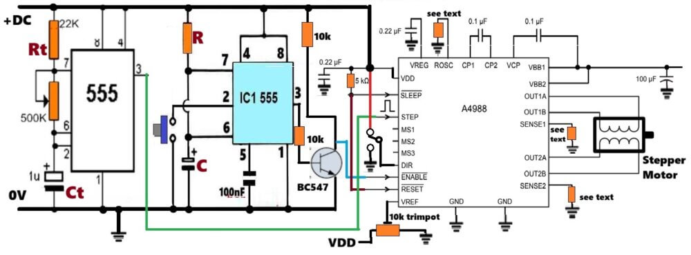
Note: Make sure all the lines and connections with the ground symbols are connected in common and then connected to the 0V supply of the power input DC.
Diagram Description
Now we start describing the diagram in a very slow way so you can imagine the whole wiring inside your mind like a picture.
The Power Supply Section
In the diagram we first see a simple power supply block where we see one positive line and one ground line coming from some DC source. We assume that this same DC source is going to feed both the A4988 module and also the 555 based circuit.
We take the +V line and we route it upward where it goes to the Vmot pin of the A4988 and also to the VM pin of that driver and connect the +V line to the Vcc supply rails of both 555 astable and 555 monostable stages after proper 5 V or 12 V regulation, depending on what supply you want.
The ground from the power supply goes to the GND pin of the A4988 and also to the GND lines of both 555 circuits.
We must share the same ground between all blocks because we want all signals to maintain a common reference level.
The 555 Astable Section

Now we move to the left side where we see the 555 astable block. This 555 astable is a simple free running oscillator that generates continuous square pulses, which are the STEP pulses.
We see that the output pin 3 of the 555 astable is going out from the block through a line marked as STEP. That STEP line finally goes to the STEP pin of the A4988 module.
Inside the astable block we will have Rt, Ct, the discharge pin 7, the threshold pin 6, the trigger pin 2, all connected in the normal classic astable configuration.
The pin 3 from the 555 astable directly feeds the STEP pin of the A4988. This pulse makes the motor rotate one step for each pulse.
Since you increase the frequency then the motor speed increases and since you decrease the frequency then the motor speed decreases.
The 555 Monostable Section
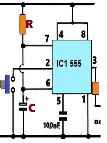
Now we move to the middle part of the diagram where we have the second 555 which is configured as a monostable. This monostable is triggered by some external push button or switch.
When that trigger comes then the monostable pin 3 gives a HIGH output for a fixed duration which you will decide by selecting the values of R and C inside the monostable.
From pin 3 of the 555 monostable, we send the signal to the ENABLE pin of the A4988, but here the ENABLE pin of A4988 is active LOW, which means that when ENABLE is LOW then the driver becomes active and when ENABLE is HIGH then the driver becomes inactive.
Because of this, we add one small NPN transistor or one inverter so that the active pulse from the monostable becomes inverted.
So when the monostable output becomes HIGH, then inverter output becomes LOW and this LOW activates the A4988 for that specific duration.
So the monostable output pin 3 travels into that inverter stage, and then from the inverter output we take one line that goes to the ENABLE pin of the A4988.
So this makes sure that the stepper motor only rotates while the monostable is timing HIGH.
The Direction (DIR) Connection Block
Now we move to the top right area of the diagram where we see the DIR pin of A4988. This pin decides the direction of rotation of the motor, so when the DIR pin is HIGH then the motor runs clockwise and when DIR is LOW then the motor will run anticlockwise.
So we take a SPDT switch or any toggle switch and we connect its center pin to the DIR input of the A4988.
The two side terminals of that switch are connected to +5V and GND respectively, so when we flip the switch one way then DIR gets +5V and when we flip it the other way then DIR gets 0V. That decides the direction of rotation.
The Motor Output Block
Now we go to the extreme right side of the diagram where the stepper motor is shown. This is a Bipolar stepper motor, so we have two coils, coil A and coil B.
Coil A is connected to A1 and A2 terminals of the A4988 module, coil B is connected to B1 and B2 terminals of A4988.
The A4988 will automatically energize the coils in the correct sequence based on the STEP pulses and the DIR level that we decide.
The motor supply lines Vmot and GND come from the main power supply. The current limiting is done through the Vref pin of A4988 using a small onboard potentiometer.
We leave Vref as per your choice of setting. You can adjust it or keep it open depending on your design, but the safest method is to set it with the potentiometer to limit coil current.
The Overall Signal Flow
Let us imagine that the 555 astable is continuously sending STEP pulses to the STEP pin of A4988, but the A4988 will not do anything because ENABLE is HIGH normally.
When a push button triggers the monostable then the monostable output goes HIGH for some seconds, and that HIGH passes through the inverter and becomes LOW at the ENABLE pin.
So A4988 becomes active only for that time. Now every STEP pulse coming from the 555 astable makes the motor rotate. The rotation direction depends on the DIR pin controlled by the SPDT switch.
So the diagram is basically showing how we connect the timing block (555 monostable), the pulse block (555 astable), the direction block (switch), and the driver block (A4988) in one simple understandable flow.
Why This Circuit Works Without Microcontroller
Since A4988 already has the complete microstepping logic inside, so we do not need any microcontroller.
The only things needed are STEP pulses and DIR selection. The 555 easily provides continuous pulses. The SPDT gives direction. The monostable gives timing, So the circuit becomes extremely simple and robust.
Setting Vref Correctly
We also remind that the user must set Vref correctly, so when Vref is high then the motor pulls more current and gets strong torque but more heating.
When Vref is low then the motor draws less current and torque reduces, so the Vref adjustment must be done carefully.
Applications
We can use this simple A4988 + 555 circuit for small XY table, miniature camera mechanism, hobby robot, indexing mechanism, or any small two phase stepper motor.
Conclusion
So in this whole explanation we understood how we can create a very simple stepper motor controller using only one A4988 module, one 555 pulse generator, one SPDT switch and one timer stage. We also understood that direction control is through DIR, speed control is through STEP frequency, and current control is through Vref. We also saw that we can run the motor for a specific time using a 555 monostable stage.


Comments
Hi Swagatam, Would it be possible to drive this circuit with just the direction switch?
ie have the timer start when the direction is changed, without having to press a second button?
Hope you can help
Regards
David Groom
Hi David,
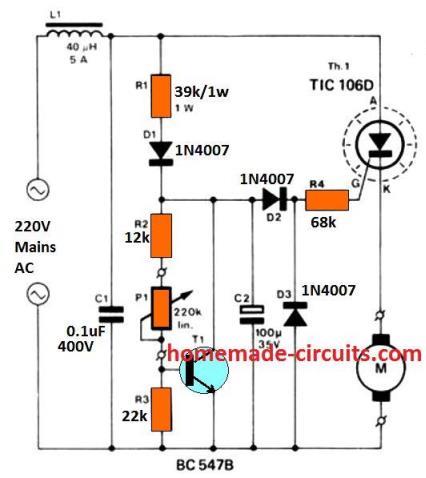
I think you can try the following circuit for achieving the intended results, Just replace this circuit with the existing 555 monostable stage in the design:
https://www.homemade-circuits.com/wp-content/uploads/2025/12/monostable-wth-ON-OFF-toggle-switch-trigger.jpg
Please let me know if it works for not?