This is perhaps the most simplest looking LED flasher that does not depend on any semiconductor. This LED blinker circuit utilizes ordinary passive components like a few resistors, a capacitor and an LDR. Meaning, this LED flasher does not depend on transistors or ICs to create the blinking effect.
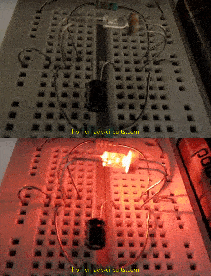
Circuit Description
The LED-LDR combination is utilized to work like an amplifier. As the current through the LED increases, it decreases the resistance of the LDR, which in turn causes the voltage at the right side (output) of the circuit to increase.
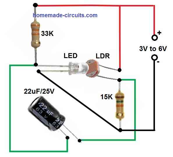
As long as the voltage at the "output" of the capacitor continues to rise, the LED derives a positive feedback from the capacitor's charging current.
The charging of the capacitor inhibits when the output voltage attains a level that is nearly equal to the supply voltage, and the LED gradually fades.
As a result, the output voltage decreases and the LDR resistance rises. The LED eventually fully switches off through the charged capacitor.
The capacitor is discharged as a result of the left resistor. This feeds a some current to the LED that gradually causes the LED to become slightly positive biased once again. As the process repeats, the LED brightness intensifies.
The oscillator employed in this LED/LDR blinker circuit resembles a relaxation type of oscillator.
Use a high intensity LED that sticks to the LDR face to face within 5mm distance. This is necessary to provide enhanced gain to start the blinking effect. The red LED chosen in this setup was a standard high bright type of LED with a 3700 mcd @20mA luminosity specification.
As you can see in the GIF image at the top, it is not necessary to have a completely darkness to initiate the blinking process. The blinking process will continue to happen even in a semi-dark environment.
However, if the ambient light is increased the blinking will stop.
This is because, in bright ambient light conditions the LDR resistance becomes very low causing the oscillation to stall and the blinking effect stops.
Parts List
- Resistors are 1/4 watt 5%
- 33 K - 1no
- 15 K - 1no
- LDR - 1no, any standard type as indicated in the diagram
- LED - 1no, any 20 mA high bright LED
- Capacitor
- 22 μF/25 V Electrolytic - 1no
Power Supply
The LED/LDR blinking circuit works with a 3V supply which can be provided from a small AC to DC 3 V adapter or from a couple of series AAA 1.5 V cells.
You can also try using a mobile charger power supply for powering the circuit and check the response.


Questions & Answers
Hello Swagatam.
I’ve known your site for years, congratulations on your work.
I haven’t tested it yet, but looking at the circuit, the resistor values caught my eye. For example, you’ve marked it as 33kΩ for a supply voltage of 3VDC (and 15kΩ for the capacitor’s reverse discharge). Even if it’s in the Ultrabright class, how is it possible for this LED to glow under 3V with a resistor of this value?
I know very well that some LEDs produced in recent years can give good brightness at very low currents. It’s possible to find these occasionally in my country, but not all of them. Even in this case, 33kΩ for 3V seems a bit excessive to me. Could you have missed something important when building your circuit?
What do you say?
Thank you Seron, I greatly appreciate your kind words!
yes at first glance it really looks impossible because 33K should severely limit current.
However, this circuit does not drive the LED in a continuous DC mode. The 33K resistor only provides a very small initial bias current of maybe around 30uA. Even that tiny current can produce a faint light, which is enough to reduce the LDR resistance.
Once the LDR responds, then capacitor (22uF) and the 15K resistor take over and create a charge–discharge cycle. During these transitions, short current pulses flow through the LED which are much higher than the steady 30 µA. These brief pulses make the LED appear to blink.
So the 33K resistor does not control the brightness. It only initiates the feedback loop, while the actual blinking is produced by the interaction between the LDR, capacitor and the timing network. The LED current is now influenced by the capacitor + LDR network, not just the 33K.
Hallo again Mr.Swagatam.
Sorry – instead of a Worldwide discovery You make a mistake – the Your cirquit’s LED in did is a unit of LED with a blinking microchip inside of the bulb – thats why the cirquit can work ONLY. I tesed the cirquit by calculations – it must not work. For case of “some non-described feachures of a LED” I test the cirquit with a lot of epitaxial LEDS – red, green, white (UV-luminophorus whide visible spectrum), with 1 LDR (20 ohm at direct light of sun at midday till 1MegaOhm at dark) with 2.2-33UF few capacitors (6 stages) with both resistors 100KOhm-adjustable 3-pin potentiometers with supply 3xAA size battary =4.5V nominal – all was not worked with any set of parameters. The cirquit could work if were LED have a dinistor’s feachures, Sir.
Also – colors of resistors at Your picture – black/green/red/gold mean 1/5/2 or1/+-5% i.e. 1k5 ohm =1500 ohm +-5% – not a 15kiloOhm described Your! Same about left = connected to LED’s pin resistor – colors red/red/red/gold mean 2/2/2/+-5% i.e. 2K2ohm =2200 ohm +-5% – not a 33 KiloOhm!
Hello Igor,
I think you are mistaken, this circuit will certainly work, with any standard LED.
The 15k resistor has brown, green, orange bands, and the 33k resistor has orange, orange, orange bands, you can get it confirmed by anyone around you.
So please try with 15k and 33k resistors and using a good quality LDR, the circuit will work for you….all the best to you…
can you please explain how a single blinking LED works? It must have an internal transistor as well al other components? does it use negative resistance of the transistor or is it a full oscillator circuit?
Hi, I think these LEDs have an in-built chip-on-board circuit which include very tiny or minute embedded circuitry having resistors and capacitors, which are intricately configured to generate the flashing effect on the LED.
Hi,
Can you or anyone you know mentor children interested in electronics? My son does small circuits but he needs further guidance to understand concepts and do experiments. May be some thing like a 30 min session every week for a fees. Thanks
Hi, I appreciate your interest. If I find anyone who can fulfill your request, I will surely let you know. Alternatively, if you have any questions regarding electronics you can feel free to ask me here.
can i change the delay time of the blinker by putting a 100k pot instead of the 15k resistor
Yes, according to me that should work, just make sure to put a 1K series resistor with the pot.
I tried making something like this to use as a driver circuit for the base of a transistor or mosfet used in a dc-dc boost application…but never put together a finished circuit that worked.
It would be nifty if you showed how to add that to this little circuit.
The garden light solar walkway lights will flash at just the right voltage, too (around .80 on a AAA cell) but I have tried to get the 5252 or the other 4 pin chips to oscillate by using an rc network to the solar input pin. They work for a while but never last.
I don’t think the above circuit could be used as an oscillator source for driving another transistor, because the circuit does not produce 0 V during its OFF periods, while transistor would require a perfect 0 V to switch OFF. Moreover a boost application would require a high frequency which the above circuit cannot produce.