In this post I have explained and tries to solve a common car door opening issue which may be seen in quite a few old model cars. The proposed circuit of a car door close optimizer was requested by Mr. Mark Rothwell.
Technical Specifications
Just stumbled across your site, hope you can help/advise me?I have a 1999 Mercedes SLK and it has a well-known design flaw, the doors are frameless and the windows have the closed position set mechanically by a small metal bracket glued to the window within the door which stops the window at the correct position when closed so when the doors are opened and closed the window just catches the rubber seal as the door closes and allows the window to slide into the recess.The problem is these brackets fall off allowing the window to close a couple of mm higher than designed which isn’t a problem for the window mech but this causes the window to catch on the rubber door seal and not sit into the seal recess properly, the only way to close the door properly is to drop the window slightly before closing the door.The door seals on my car are being worn out by the window rubbing on them when the door is closed and the on closing the window is being held on the outside of the door seal so I had an idea to incorporate a timer circuit to drop window few mm on opening the door then close it again after the door is shut, ideally to be activated by the ground signal for the interior lamp (i'm assuming its a ground sig but haven't checked yet)BMW 3 series (and poss others) have for many years had such a system incorporated in the car at manufacture that drops the window a couple of mm when the door is opened and closes the window when the door is closed and I think this car should have had this system when designed!My idea is to use a 555 timer circuit to achieve this but the last time I dabbled in circuit design was over 20 years ago and it is giving me a big headache trying to remember the theory, any help or advice would be much appreciated and although most modern cars have now taken BMW’s initiative and now include this function there may even be a market out there for such a seal saving device on older cars?
How the Circuit is Supposed to Work
1) Door opens, ground signal applied from door switch
2) Momentary energises relay or output to apply +12V 20A for approx 500 milliseconds (this time may need to be adjusted when fitted) to momentary send the window down (open) a fraction (this output to be connected to the window open button of the car)
3) On closing the door, ground signal removed
4) Momentary energises relay or output to apply +12V 20A for approx 1 second (this time may need to be adjusted when fitted) to momentary send the window up (closed) (this output to be connected to the window close button of the car)
Any advice much appreciated!
Mark
The Design:
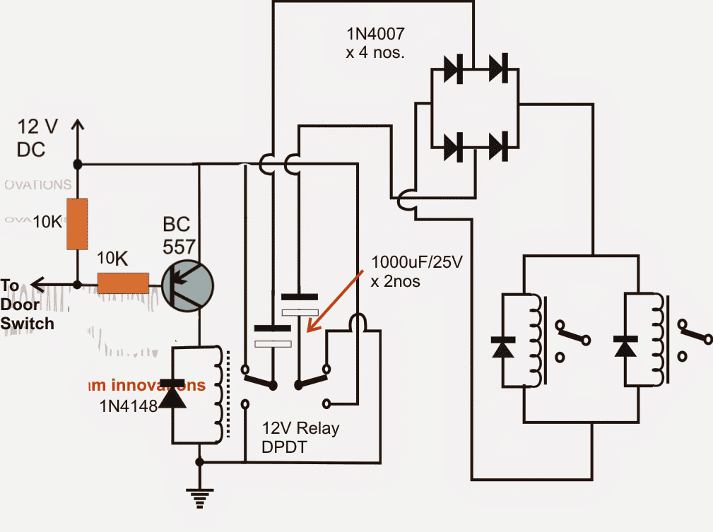
The presented car door close optimizer circuit is simple enough, and self explanatory. As soon as the car door is opened, the transistor receives the required negative base bias triggering the attached DPDT relay.
The DPDT relay contacts along with the 1000uf capacitors are wired such that the output across the capacitors changes polarity and switches ON the load only momentarily every time the door is opened or closed.
The change in polarity is required for enabling the capacitors charge and discharge process which in turn is necessary for the required transfer of the momentary pulses to the connected load.

The above design was suitably modified by Mr. Mark, I have explained more about it:
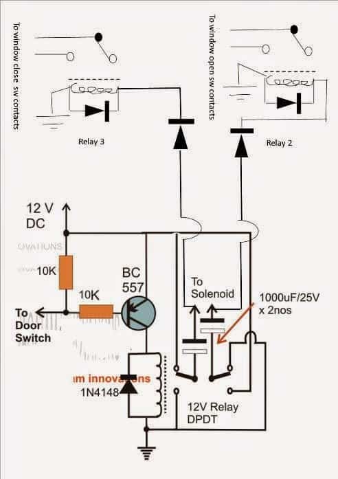
I was intending to connect the circuit to the contacts of the window switches, ive attached a jpg with some additional components, I think this will work with the additional relays using the solenoid outputs to drive 2 relays when each of the outputs are high and the capacitors giving the required cut off releasing the relays 2&3 that I’ve added at the correct timing.
The diodes I’ve added after the original solenoid outputs in your circuit are to protect the electrolytic from reverse polarity with the GND presented through the coils of relays 1 & 2 when the first relay is not energised (but I’m not completely certain they are needed?).
Its not shown on the diagram but I later thought I could achieve a slight extension to the close relay energised time by adding an electrolytic cap across the relay coil of relay 3 and this will ensure the windows are always fully closed when the door is shut.
Something I have realised is when the windows are open in summer it means the circuit will always close the windows slightly when closing the door but I think that is a minor problem compared to currently wearing out the seals and the door not closing properly,
If everything works well I may look to see if I can tap a signal from somewhere that I can use to over ride the circuit when the roof is dropped or windows are lowered.
I will have to get it built and test and will let you know.
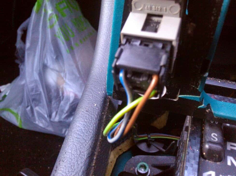
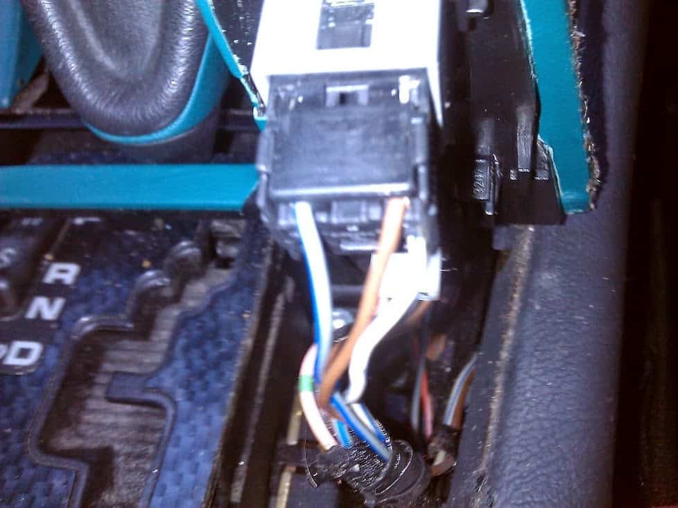
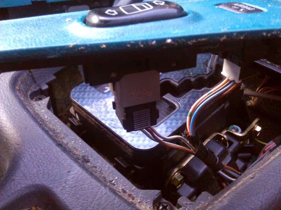
Following are some wonderful images and video sent by Mr. Mark, backs up the above discussion, and provides a clearer view of the involved operations.
Image and video courtesy: Mr. Mark Rothwell
Wiring Correction
A closer inspection shows that the modified circuit of the door close optimizer sent by Mr. Mark needs a major correction otherwise it won't work as intended.
The issue is in the termination of the 1000uF capacitor to the car relays.
Since the capacitors and the circuit relay are designed for a dual polarity function, needs to be implemented such that the car relays are able to switch momentarily in response to both ON/OFF conditions of the circuits DPDT relay.
The inclusion of a simple bridge diode network in between the capacitor outputs and car relays effectively solves the issue as shown the following finalized diagram


Questions & Answers
Hi Swagatam,
thks for your reply.
but i don’t want, and don’t think that’s a good idea, having control directly over the hydraulic pump of roof.
It has too many variables, and ecu controls all of it (battery state, if low, won’t operate, hydraulic temperature, motor temp, all the roof switches (more than 12) and so on).
Maybe a simple circuit, that its connect to ABS and SPEED Sensors (all cars now, have this), and convert it to …say to voltage, some “frequency to voltage converter”, and if it exceeds the pre regulated value of Voltage, disconnect the circuit, testing it before with some potentiometer, and after the desired value, replace it with a fixed resistor… just a thought.
The frequency of this it’s 3hz when rolling slow or parked, and after that it goes to 21hz, which block the operation.
I just like a simple thing, to control this, as i said, i have bypass this by-force, it opens the roof, from my tests at 100kms/h, and if the speed is higher, it will open too, but the structure of it, it is not designed to that “wind force”.
Do you have any frequency to voltage circuit, so i can make it on breadboard and test it?
Thanks for your time.
Cheers,
Roberto
Hello again,
No, if you look at this pic: i.ebayimg.com/images/g/KUQAAOSwDKtY1w1o/s-l1600.jpg
on pins 56 its ABS sensor and on 74 its the SPEED sensor, i have it hijacked, this way: cut both wires, on ecu side shunted both, in the end of the shunt, add a small resistor (200~600ohm 1/4w, will do the job) in the other end of resistor solder the speed sensor, leave abs wire unconnected. since “vital signals” from this are connected before they get on ecu (to speedmeter, to ABS system, ESP (stability System) ) it’s not a problem for the safety of the car.
it’s only very light signals that go here, in the bottom of pic, you can see too, the larger pins, its where are the relays for windows, on top, for example windshield and water spray relays, this way, i have the roof opening at any speed!
Just remember, before i got arduino, controling roof and windows with original key, have been playing with a 4017, to “read” the signals from fob input… and it’s a quiete interesting IC…. feeding it with the car pulses abs or speed or both, and using, not the firsts outputs, but middle or last… maybe i get a simple circuit divider…
have to measure the voltage in those wires, maybe… its 12v like the rest of it, but like its a only a signal, using a transistor to have 12v again, on output of 4017, and inject the signal again on ecu… what do you think of this ? the frequency it’s low… max of 21hz, so no special transistor needed, i think.
Cheers,
R.
Sorry for late answer, but have been a little busy, i’m fine tunning a Cheap Remote Fob Roof and Windows using arduino, you can see it here: https://www.youtube.com/channel/UC0Ly0UW-AOGnUHxjq-4hH7Q/featured and here, in older posts have my first tests https://vimeo.com/slkr170, in one of them, you could see the Uno and some shields, laying on dashboard. The commercial versions of this, go far more than 300€.
back to the subject… can i/how replace the meter, and use some kind of circuit, if voltage gets to a value, trigger a relay (DPDT).
this way, the “bypass” speed is always active, the speed and abs sensors are by default on NC relay pins, when the speed gets higher, example 50kms, it activate relay, and it goes as a standard connection, as the wires never been cut.
If i could upload some jpgs, it was easier to see, than i can describe it.
Never use a frequency to voltage, but i think… freq. goes high… voltage too; is that how it works?
Regards,
Roberto
The signals from Abs and Speed Sensor, connect to ecu box, since i have already cut those two to hijack the speed limitation, my idea of putting the converter of volt./freq. between the wires that i cut from car loom and ecu box (where they already have been cut).
maybe will need to make two converters, one for each line (abs/speed sensor) have to investigate a little more. I had a small oscilloscope, hope i can “see” how it behaves.
R.
Have to try it… 🙂

with a multimeter on a buzzer position, and car parked…, you can hear the “pulsing” . have to pull the wires inside the car, and test it while driving, to get an idea of how it behaves.
I think some how, don’t know it yet, it should work.
if you take a quick look on schema, on left side, there’s a relay (the only one) and it seems to me, its connected as i intend do it.
where Abs= abs signal and Tacho=Speed Sensor, the IN and OUT refer to before cut and after cut. This is the only available schema online… but i think they all work the same way, the commercial versions of this, all cut both wires to control the speed of opening the roof.
Cheers,
R.
Ok great :), if you are sure then you can go ahead with it, but the circuit will need a 12V supply to function
I don’t think the F to V converter will work in that way, the converter will have to be fed with a frequency at its specified input, and it will have to be supplied with a separate operating voltage, and its output will need to be configured with a transistor stage for generating the required cut-off signals whenever a high frequency is detected……
I am afraid, by inserting it between the wires will not help
OK thanks, understood, yes a frequency to voltage converter will do this for you, but from where would you access the frequency input for the converter?
sorry, I am having difficulty interpreting the whole design quickly, you said you needed a frequency to voltage converter which I provided you in the last comment, so how do you plan to use it with your existing system?
That’s a good idea Roberto, controlling the frequency externally without disturbing the internal circuitry is definitely possible using a frequency to voltage converter circuit such as the following one:
https://www.homemade-circuits.com/2012/05/make-this-simple-tachometer-circuit.html
You can use the last circuit, its output will proportionately rise as the input frequency rises.
More can be obtained under this link:
https://www.homemade-circuits.com/?s=tachometer
But how do you plan to get the frequency data, is it through some kind of wheel and slot arrangement?
Hello again, Swagatam
I see that you publish my comments about this, if you want to illustrate it better, i can send some fotos of disassemble switch, the ecu box open, for better seeing the relays that controls the windows (rears (small) and mains windows). when i have a little time, will investigate if the doors switches will connect to ecu, or if to pse pump, on this car, there are not electric locks, all the locks, work with air pressure.
let me know, if you want them.
For the same car, i’d like you opinion in a circuit to bypass a limitation of it: it can only open the roof, if the speed it’s very low, there are two wires, that go to the same ecu box, one from ABS, and the other from Speed Sensor, have bypass this, but i’d like a more “elegant way” to this, the way, in the way i have it, it opens the roof at any speed, because the signal wire it’s cheated. I would like if i can, somehow to “adjust it”, so it can operate only until 30miles/50kmh. it’s a lot of stress to it.
This guy, a long time ago made it, and put some thoughts about it, schemas, pcb design, code, components, etc
it’s better to use google translator, because it’s in german, can’t read it, and the english part, doesn’t contain all the info
http://www.simpleroof.de/?Projekte:EasyRoof_SLK_R170:Funktion
full diagram of it
http://www.simpleroof.de/?Projekte:EasyRoof_SLK_R170:Schaltplan_%26amp%3B_Layout
there’re a page with code too.
If you can propose, some kind of idea to this will appreciate it.
Or how much do you take, to make it.
Sometime ago, i would like the whole circuit, but like i had two arduinos in draw, decide to give them a try, two weeks later, already have it connected to the car, to do some real tests. took another two, to learn some more about it and fine tune, the openings of roof, windows, car lock, simulate the ignition on #2 (the only way, the roof its activated).
Thank you.
Keep the good work. 🙂
R.
Hi Roberto,
if your basic requirement is to operate the motor with a controlled speed, then this could be done through a simple IC 555 PWM circuit as shown in the following article.
https://www.homemade-circuits.com/2012/05/make-this-pwm-based-dc-motor-speed.html
instead of feeding the motor with a direct DC from the ECU, make it through the above circuit and this will allow the motor to run at the desired controlled speed as per the setting on the potentiometer
the circuit that you have referred looks huge and it won’t be possible for me to go through it due to lack of time, sorry about that, if time permits I will surely take a look into it.
The Slk, at least the R170 model, uses a one wire control for windows, 200/220ohms go up, 740/820ohms go down. the relays for windows are inside ecu box, and solder in pcb.
they’re miniature double coil relays, double circuit.
The values of 200 and 740ohms, you get them, if you remove the switches from the car, and measure them. that’s how i discover how to control them. i have use the commercially available near values. if you shunt to ground the wire from window it goes down at once.
If you want to do both at once, need to use a pair of diodes (signal diodes, will do), in each wire, join them in the ends and use a 100ohm resistor. all resistors 1/4w. it’s just a signal, the heavy load its take care by the relays (8amps when moving, and then +/- 15amps, when they reach the down or up, then the ecu disconnect them)
the windows switches have only 3 wires in this car:
1 ground
2 illumination (illuminated switches)
3 window control (it’s the only one that matters)
R.
Thanks for this interesting information, appreciate it!!
Hello sir swagatam
How can i contact you.i need youre help with this.i want to build a window control.
Best regards
[email protected]
Ruben, please feel free to tell me the details here, I'll try to help you out.
Sir this mini video its excelent! I love it 🙂
thanks Bulent, I am glad you liked it.