A crank flashlight basically works by hand cranking a permanent magnet motor, which generates electricity for illuminating the attached LEDs.

Motor Becomes a Generator
Normally, a permanent magnet motor is used for executing a rotational movement by applying a DC potential across its specified supply terminals.
However we also know that the same motor can be easily converted into an electricity generator by reversing the operations, meaning when its shaft is applied with a rotational torque through an external mechanical force, causes electricity to be generated across its supply terminals.
The above phenomenon is exploited in crank flashlights where the external mechanical force is achieved through manual hand cranking of a motor via gears suitably enhanced to make the operations most efficient.
So it's just about forcing a permanent magnet type motor to rotate through manual force and witness electricity rolling out from its wire ends, it's as simple as that.
Having said this, the electricity from a hand cranked motor can be very unstabilized and therefore cannot be used for illuminating LEDs without going through proper processing.
Therefore an electronic circuit becomes crucial to ensure that the electricity from the motor is correctly and safely applied to the LEDs.
From the following in-depth study I will try to explain how crank flashlights work and regarding all the necessary parameters involved within these devices for a safe execution of the operations.
Main Parts of a Crank Flashlight
A Crank Flashlight basically requires the following parts:
1) A system involving a gear box and the associated mechanism cranking arrangement.
2) a Bridge rectifier, and filter capacitor.
3) LEDs for the required flashlight illumination
5) a rechargeable battery (optional)
When you open a standard crank flashlight device, fundamentally you would be able to see all the above listed materials inside the casing, an example image is shared below for your reference:

In the image above we can clearly see all the items discussed above, the functioning of the entire system can be learned from the following explanation:
How a Crank Flashlight Works
1) When the motor is cranked with manual force (with hand), the motor begins generating electricity which flow through its wires and reaches the bridge rectifier stage.
2) The bridge rectifier ensures that regardless of the motor rotation direction the output is always maintained with a constant polarity, and the outcome is a pure DC. However this DC is full of ripples at this point
3) The filter capacitor attached with the bridge rectifier smooths the DC filters the ripples and creates a clean stable DC level.
4) This DC level is approximately equal to the motors specified operating voltage and normally this is generally around 3 to 5V.
5) For a 3V motor, the DC output can be assumed to be around 4V to 5V after rectification and filtration.
6) This 4 to 5V is directly applied to a 3.7V rechargeable cell, as indicated in the diagram. This cell is actually optional, and enables the system to store energy in it each time the mechanism is casually cranked by the user.
This stored energy in the battery becomes available for later usage for illuminating the LED simply by a press of the button switch (shown in RED), additionally this stored energy from the battery also reinforces the illumination with extra cranking by the user, for achieving an increased LED brightness.
7) If the battery is not required, the filter capacitor could be upgraded into a high value capacitor in the order of 4700uF/10V which could be preferably a super capacitor, and this enhancement can be used for replacing the battery entirely.
8) We can also see a few resistors near the LEDs, these are connected in series each LED, to ensure a current controlled supply to the LeDs, the LEDs are normally connected in parallel.
Crank Flashlight Circuit Diagram
The following schematic provides us the detailed configuration of a standard crank flashlight circuit:
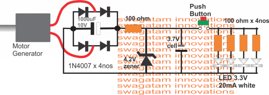
From the above explanation you might have got a clear idea regarding how a crank flashlight works using the recommended parts and a motor in the form of a generator, if you have any further doubts, please do use the comment box for expressing your valuable thoughts.
In one of the upcoming articles I have explained how to use a crank flashlight as an ever-ready 24x7 power bank circuit for your smart phones.


Questions & Answers
I have a GoPower by ideation Solar flashlight with AM/FM & Weatherband radio.
You can crank it, USB charge it or solar.
When I crank it, 20 or 100 times it wont stay charged or should it?
It should stay charged for many minutes. It means either the battery is gone or the cranking mechanism is mo longer working.
That is great to know, thank you so very much for the feedback. Very nice
So, how many cranks do you need to do to hold a charge on a flashlight? 20,100 and does it charge the battery to give you light for so long or do you have to crank continuously?
A 1 minute cranking should provide around 15 minutes of light.
I looked everywhere for that answer lol so thank you very much, I was wondering how long to crank.
SO, is there anyway I can get a replacement.? I just tried using it last month and everything else worked but the cranking mechanism. I appreciate again all you help and quick response.
I do like them a lot and want a few more for storage .
You are most welcome! If you want to buy a new replacement cranked flashlight, you can probably get one from any online store like Amazon. Before buying do read the specifications of the unit, and make sure it suits your requirement.
HI, I just kept cranking over a period of 2 days , and it works again. thanks for your helpGreg martin
Glad it’s working now!
I have CRANK FLASHLIGHT THAT HASEN’T BEEN USED IN ABOUT 6 MONTHS. it doesn’t work when it is cranked -what can I do to make it functional again ?
thank you for your help-,
Greg
What is not working in the unit? Is it the LED? You can check the output from the bridge rectifier of the unit while cranking and check whether it produces the specified amount of voltage or not. According to me it should be generating the voltage, and it is the LED that might have gone faulty.