In this post I have explained the construction of a homemade 100 watt capacitive tubelight circuit using 1 watt LEDs. The idea was requested, constructed, tested and verified by one the avid readers of this blog Mr. Tamam. Let's go through the entire discussion.
Discussing the Proposed The Design
I regularly visit your blog, and so far I have constructed several circuits from you blog. It's been a long time I am trying to build an AC LED Tube light which will run at 220-240 VAC and produce more or at least equivalent light as like a 60 Watt regular tube/florescent light, because I want to replace my room's tube light which annoy me always. I like LEDs very much because of their low power consumption rate and high brightness. I have already seen several circuits related to AC LED lights on your blog, but none are fit to my criteria. My Requirements: 1. I will use 1 Watt LED (3.3V, 10mm, 180 degree) a number of maximum 100-150 piece.2. Power Supply will be Capacitive Type with maximum protection as far as possible. I don't want to use transformer.3. Output light has to be bright as much as a regular tube light (60 Watt) like I said above. I know it's easy for you to design a circuit considering above requirements.I badly need the circuit, its my humble request to you, please take time and design the circuit for me.Sorry for my bad English & Thanks in advance !! My Reply:
I appreciate your interest, I already have the requested circuit in my blog, please check out the following link:
https://www.homemade-circuits.com/2014/04/simplest-100-watt-led-bulb-circuit.html
Feedback!
Thank you for your reply. Sorry to bother you bro, I don't understand "SMPS types NTC thermistor"
Even my local spare parts dealers did not understand. All they asked me for a value in Ohms for the thermistor, is the termistor compulsory for the circuit?
Because, I assembled and tested your circuit in project board successfully without the thermistor. If it is not compulsory then I wont use it.
Using an Inductor as the surge Suppressor
My advise is that you explain the dealer by saying that you want a thermistor that are normally used in 12V smps adapters. I am not sure about the exact ohms so can't suggest it correctly.
Alternatively you can simply eliminate the NTC and use an inductor directly in series with the LED chain, this inductor could be made by winding a magnet wire (super enameled copper wire) over any ferrite core, use 100 turns of it with 10mm diameter.
The data is not critical could be a little here and there, we simply need a coil having a resistance of 10 ohms in series with the LED...that's all.
Building the Prototype
Thank you for providing your 100 Watt LED Circuit.
After some trial and error I have successfully built the circuit but slightly modified your circuit as below:
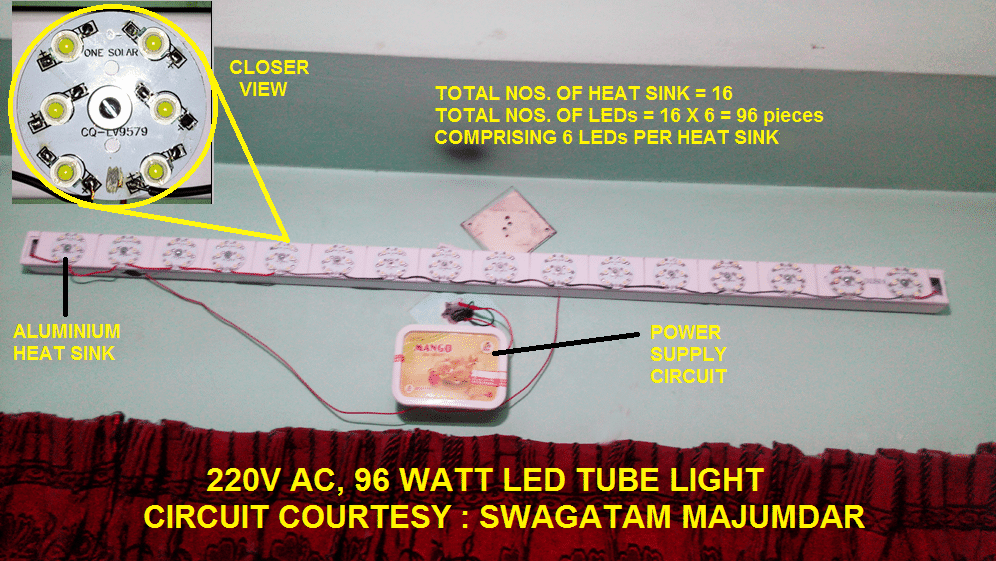
1. I have used total 96 nos. of 1 Watt high bright worm white LEDs.
2. I have changed the value of the AC capacitor in your circuit from 5uF/400V to 14uF / 400V (After putting total 4 nos. of 3.5uF capacitors in parallel) as I am not getting sufficient light with 5uF/400V.
I used bleeding resistor rated 1 Mega Ohms between leads of capacitors.
3. I have also changed the Filter capacitor next to bridge rectifier from 10uF/400V to 100uF/400V and added a bleeding resistor rated 470 Kilo Ohms across its output.
4. I have put a Varistor between incoming AC Neutral and Phase to the circuit.However, I am posting some images of the project.
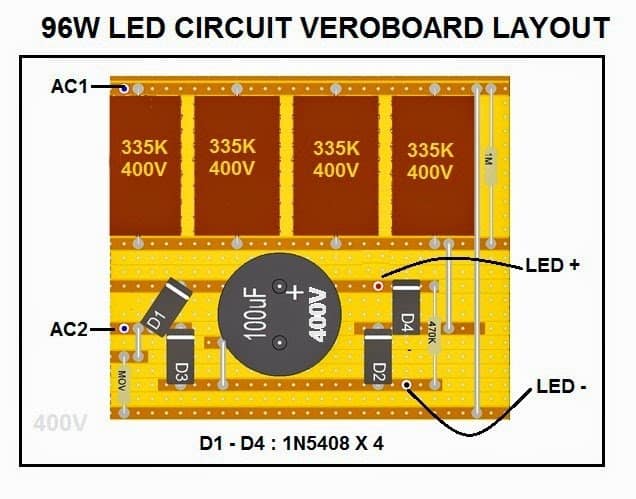
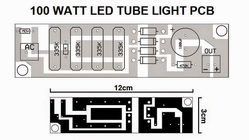
The following image presents PCB design layout for the above 100 watt LED tubelight circuit, Courtesy Mr. Abu Tamam.


Questions & Answers
Hello sir I want to run only 6 Number of 1watt led to 220v AC wat wil be the changes in Circuit
Abdul, put the LED in series with a 10 ohm series resistors.
For the input capacitor use a 4uF/400V capacitor.
Use a 5 ohm NTC at the input of the circuit.
Use a bridge rectifier for the rectification
Also make sure to put a 20 V 5 watt zener diode after the bridge rectifier
Namskar. I am senior citizen and having interest in small electronic hobby kits which can be made in Home only. One thing is important to tell you that I am only 11th std passed and having interest in electronic. I am having 70% knowledge of electronic parts only but how they work I do not know. But i can assemble them as per small circuit diagramme. I have made few projects as per Youtube information and some knowledge acquired with the help of Computer etc. Without any knowledge i also repaired small electronic circuits like chocks, bell, power supply, led tube/bulb etc. etc.
I want to get idea about following : I am having 3.7 volt lithium battery and want to use 1 watt led . I used few ( 6/10 ) led but it gets very hot due to high current I think. How much maximum 1 watt led i can use with one 3.7 lithium battery with proper Heat Sink ? please help me and give idea. Thanks
Hello, Glad to know about your interest and knowledge in the field of electronics!
1 watt LED will need minimum 300 mA current to glow at full brightness, and it can get very hot unless it is attached with a suitable heatsink and a current limiting resistor.
Assuming your 3.7 V Li-ion cell is rated at 2600 mAh, then you can connect 7 LEDs in parallel with it, each LED must have its own series resistor.
The resistor value can be calculated in the following manner
R = supply V – LED V / LED current
= 4.1 – 3 / 0.3 = 3.66 Ohms
wattage = (4.1 – 3) x 0.3 = 0.33 watts or 1/2 watt will do
You can connect the resistor with the positive pin of the LED or the negative pin of the LED.
So 7 individual resistors will need to be connected with the 7 LEDs
Dear Swagatam sir,
In local electronic dealer shops NTC and MOV is not available can i use instead of NTC n MOV , “10 Ohms 10 watt resistor sir “
Dear Nazim, that will not be reliable, you can add a 310V 2 watt zener across the bridge output this will effectively control the volatge and will help preventing LEDs from burning. this can be done for 93 LEDs in series.
Dear Swagatam,
Again asking on Capacitor Based LED Tubelight Circuit Using 1 Watt LEDs.
i know its not your circuit design but your having ocean knowledge on Electronic Electrical so asking again please take a some time for me from your busy schedule (take your own time i will wait) provide me some information sir.
Confirm parts
Part6:- MOV? Need Value r type (MOV infomation)
“Mov is metal oxide varistor…it blocks surge current during power switch ON”
LED7:- How should i have to arrange led (1to96 in series or combination of series and parallel)
Your Knowledge skills make it easy for me know each and very part information, i dont know about making circuit after fallowing your blog i have learn many thing from your post sir thanks a lot sir . I’m proud to have learned some of these qualities from you. Thank you for guiding me professionally and personally. “Sorry for my bad English”
Name :- Nazim
Email:- nazimhussainisyeds@gmail.com
Hello Nazim, the pictures are correct, but showing pictures will not actually help, because the parts can come in different colors, slightly different shapes, and different sizes…it is the printed value which is important and is what you must verify.
MOV can be a 330V/1amp MOV, but MOV will not guarantee 100% safety neither will an NTC.
as shown in this diagram : https://www.homemade-circuits.com/2014/04/simplest-100-watt-led-bulb-circuit.html
all the LEDs should be connected in series.
I’ll be deleting the picture links because I normally do not post external links in the comments.
Dear Swagatam sir thanks a lot for your quick reply.
All leds should me in series connections sir.
Can i reduce 93led to 40 r 50leds sir
Could you mail your whatsapp no r mobile no in my email id i have some doubts to asked. Don’t mind
My email id : nazimhussainisyeds@gmail.com
Dear Nazim,
the above design is not my design so I cannot comment on this design.
My design can be seen in the following link
https://www.homemade-circuits.com/2014/04/simplest-100-watt-led-bulb-circuit.html
sorry I am available only through this website…you can feel free to discuss your doubts here.
Your comment is awaiting moderation.
Dear Swagatam,
Thank you for providing your 100 Watt LED Circuit.
Im little bit 8t confuse can you clarify me
How many watts Resistor should i use in this circuit
1.I used bleeding resistor rated 1 Mega Ohms between leads of capacitors.
(1Mega Ohms resistor) Watts?
2.added a bleeding resistor rated 470 Kilo Ohms
(470kIlo Ohms resistor) watts?
3. What is “MOV” in this circuit
Contact details name : Nazim
Email: nazimhussainisyeds@gmail.com
Nazim, 1M can be 1 /4 watt rated
470K can be also 1/4 watt rated
MOV is metal oxide varistor…it blocks surge current during power switch ON.
Dear Sir,
1) Kindly clarify: In the above circuit, the 6 LEDs of 1w are connected in series or in parallel? What I could see is that, a set of 3 leds are in series and per heat sink there are two sets of 3 leds in series, is is correct?
2) total 4 x335k x rated capacitors are used in the cirCuit. So it is coming to about 13.2uf and the current may be 13.5 x 70 m A=13.2*70=924 mAmps. How the cirucuit is withstanding such higher current if all the LEDs are in series and the current of each led is limited to 150 m amps.?
Dear VG,
According to the figure it appears that 6 LEDs are connected in parallel, and 16 of these parallel sets are connected in series, each of the 6 parallel LED would consume around 300 x 6 = 1800mA, which would be also consumed by the whole string of 16….therefore the total rating would be 1800mA or 1.8 Amps
by the way each LED is rated at 350mA and not 150mA
You are correct sir.
Hii swagatam.. i have made this exactly however no led turing on. On measuring the output dc its only 193 volt while input ac is 220 . Where is the fault. Dc output must be around 310 . Pls tell me
Hi Webmaster, check the polarity of all the LEDs, one of them might be wrongly positioned…. remember the input capacitors must be calculated as per the LED current rating….
I want this circuit voltage & amps
300ma…300V
Thanks a lot for your immediate response but sir please reffer me the 12v/2amp SMPS circuit design
I would suggest you buy it from the market because making it could be quite difficult, it would cost you hardly a couple of 100 bucks.
Hello sir,
I want to make a led light using 10 nos of 1w led(3.4v, 350ma) to replace a 15w cfl. So will u please design a circuit…
Tanking u in advance
Hello Sarada,
connect three LEDs in series with a 6 ohm 1 watt resistor…make three such strings and connect them in parallel….now you may join the common ends of this parallel assembly with a 12V/2amp SMPS supply….make sure the LED assembly is done over a large aluminum heatsink. for more info you can refer to the following article:
https://www.homemade-circuits.com/2013/12/how-to-use-aluminum-strip-heatsink-for.html
Please tell me how can I discharge 33kv transformer from resistor..of which type,voltage,wattage and where I can find it
You may have do it with some trial and error. Try making a resistor using a 2 meter long unplated iron wire (1mm) wound over a firm mica former…you can increase or decrease the length of the iron wire as per the results
It is to be used for discharging unplugged transformers with the help of "insulating discharge sticks"
I'll require more info regarding the application for figuring it out, so pls provide it.
Can we place LED at some distance as you placed all LED on one aluminium strip? I want to placed all 96 LED on ceiling of some distance you will get idea as one video already upload on you tube as title" Living Room ceiling LED lighting project"! any effect as we place wire between two Led like brightness?
….for a 100% reliable operations I would recommend an SMPS power supply instead of a capacitive type.
The calculations may be learned here:
https://www.homemade-circuits.com/2013/02/make-this-1000-watt-led-flood-light.html
Ashok, with 144 meters the later LEDs in the string may get affected. I am not sure how much resistance a 144meter copper wire would produce, you could probably make it practically and check, however some resistance will ensure better surge protection for the LEDs, so it could be an advantage in disguise.
yes sir actually i want to use in Hall ceiling light for that please check video on youtube as title "Living Room ceiling LED lighting project " you get idea, actually what i want.
Ashok, 1.5meters x 96 = 144 meters, please let me know how you are trying to implement on this much distance, is it some kind of Hall or playground where you want to place the LED string??
The caapcitor must PPC type, non polar strictly.
Sir i want to place each LED at 0.5m to 1.5m in between same distance. There is effect of wire resistance on brightness? I saw one video on youtube as title "Living Room ceiling LED lighting project " please see this video you get idea what actually i want. another question what type of capacitor you used in above circuit? & what is min & maximum no of LED can use?
you can put some distance between the LEDs that won't affect its performance.
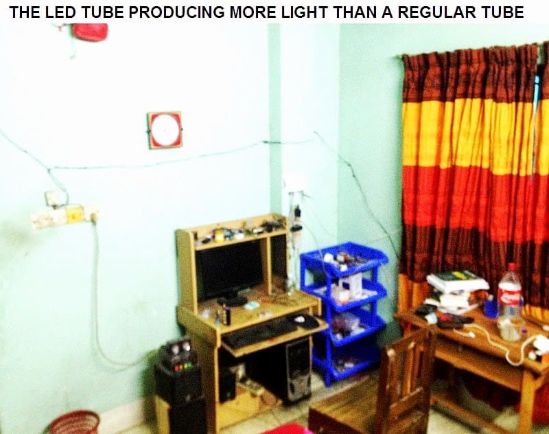
Best capacitive power supply I have ever used. I keep on this light for 18 hours a day.
I am fascinated with it's high brightness.
Thank you dear Swagatam, all credits goes to you.Tremendous calculation of using full efficiency of CPS and binding per LED to a constant voltage so that surge voltage will have no effect.
Thanks so much Tamam! It's my pleasure.