Photodiodes and phototransistors are semiconductor devices which have their p-n semiconductor junction exposed to light through a transparent cover, so that external light can react and force an electrical conduction through the junction.
How Photodiodes Work
A photodiode is just like a regular semiconductor diode (example 1N4148) consisting of a p-n junction, but it has this junction exposed to light through a transparent body.
Its working can be understood by imagining a standard silicon diode connected in reverse biased fashion across a supply source as shown below.
In this condition, no current flows through the diode except some very small leakage current.
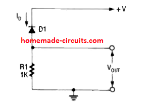
However, suppose we have the same diode with its outer opaque cover scraped of or removed and connected with a reverse bias supply. This will expose the PN junction of the diode to light, and there will be an instant flow of current through it, in response to the incident light.
This may result in a current as much as 1 mA through the diode, causing a rising voltage to develop across R1.
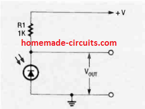
The photodiode in the above figure can be also connected on the ground side as shown below. This will produce a opposite response, resulting in a decreasing voltage across R1, when the photodiode is illuminated with external light.
The working of all P-N junction based devices is similar and will exhibit photo-conductivity when exposed to light.
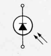
The schematic symbol of a photodiode can be see below.
Compared to cadmium-sulphide or cadmium-selenide photocells like LDRs, photodiodes are generally less sensitive to light, but their response to light changes is much faster.
Due to this reason, photocells like LDRs are generally used in applications that involve visible light, and where the response time does not need to be quick. On the other hand, photodiodes are specifically selected in applications that require fast detection of lights mostly in the infrared region.
You will find photodiodes in systems such as infrared remote control circuits, beam interruption relays and intruder alarm circuits.
There's another variant of photodiode which uses lead-sulfide (PbS) and there working characteristic is quite similar to LDRs but are designed to respond only to the infrared range lights.
Phototransistors
The following image shows the schematic symbol of a phototransistor
The phototransistor is generally in the form of a bipolar NPN silicon transistor encapsulated in a cover with a transparent opening.
It works by allowing light to reach the PN junction of the device through the transparent opening. The light reacts with the exposed PN junction of the device, initiating the photoconductivity action.
A phototransistor is mostly configured with its base pin unconnected as shown in the following two circuits.
In the left side figure the connection effectively causes the phototransistor to be in the reverse bias situation, such that it now works like a photodiode.
Here, the current generated due to light across the base collector terminals of the device is directly fed back to the base of the device, resulting in the normal current amplification and the current flowing out as the output from the collector terminal of the device.
This amplified current causes a proportionate amount of voltage to develop across the resistor R1.
Phototransistors may show identical amounts of current at their collector and emitter pins, due to an open base connection, and this prevents the device from a negative feedback.
Due to this feature, if the phototransistor is connected as shown at the right side of the above figure with R1 across emitter and ground, the outcome is exactly identical as it had been for the left side configuration. Meaning for both the configurations, the voltage developed across R1 due to phototransistor conduction is similar.
Difference between Photodiode and Phototransistor
Although the working principle is similar for the two counterparts, there are a few noticeable differences between them.
A photodiode may be rated to work with much higher frequencies in the range of tens of megahertz, as opposed to a phototransistor which is restricted to only a few hundred kilohertz.
The presence of the base terminal in a phototransistor makes it more advantageous compared to a photodiode.
A phototransistor can be converted to work like a photodiode by connecting its base with ground as shown below, but a photodiode may not have the ability to work like a phototransistor.
Another advantage of the base terminal is that the sensitivity of a phototransistor can be made variable by introducing a potentiometer across base emitter of the device as shown in the following figure.
In the above arrangement the device works like a variable sensitivity phototransistor, but if the pot R2 connections are removed, the device acts like a normal phototransistor, and if R2 is shorted to ground, then the device turns into a photodiode.
Selecting the Biasing Resistor
In all the circuit diagrams shown above the selection of R1 value is usually a balance between voltage gain and bandwidth response of the device.
As the value of R1 is increased the voltage gain increases but the useful operating bandwidth range decreases, and vice versa.
Furthermore, the value of R1 should be such that the devices are forced to work in their linear region. This can be done with some trial and error.
Practically for operating voltages from 5V and 12V any value between 1K and 10K is usually sufficient as R1.
Darlington phototransistors
These are similar to a normal darlington transistor with their internal structure. Internally these are built using two transistors coupled with each other as shown in the following schematic symbol.
The sensitivity specifications of a photodarlington transistor may be approximately 10 times higher than that of a normal phototransistor. However, the working frequency of these units are lower than the normal types, and may be restricted to only some 10s of kilohertz.
Photodiode Phototransistor Applications
The best example of photodiode and phototransistor application may be in field of lightwave signal receivers or detectors in fiber optic transmission lines.
The lightwave passing via an optical fiber can be effectively modulated both through analog or digital techniques.
Photodiodes and phototransistors are also widely used for making detectors stages in optocouplers and infrared light beam interruption devices and intruder alarm gadgets.
The problem while designing these circuits is that, the intensity of light falling on the photo sensitive devices could be very strong or weak, and also these may encounter external disturbances in the form of random visible lights, or infrared interference.
To counter these issues, these application circuits are normally operated with optical links having a specific infrared carrier frequency. Moreover the input side of the receiver is reinforced with a preamplifier so that even the weakest of the optical linking signals is detected comfortably, enabling the system with a wide range of sensitivity.
The following two applications circuits show how a foolproof implementation can be done using photodiodes through 30 kHz carrier modulation frequency.
These are selective preamplifier based photodiode alarm circuits, and will respond to a specific band of frequency, ensuring a foolproof operation of the system.
In the upper design, L1, C1 and C2 filter out all other frequencies except the intended 30 Hz frequency from an infrared optical link. As soon this is detected it is further amplified by Q1, and its output becomes active for sounding an alarm system.
Alternatively, the system could be used for activating an alarm when the optical link is cut off. In this case the transistor may be kept active permanently through a 30 Hz IR focus on the phototransistor Next, the output from the transistor could be inverted using another NPN stage so that, an interruption in the 30 Hz IR beam, turns OFF Q1, and turns ON the second NPN transistor. This second transistor must integrated through a 10uF capacitor from the collector of Q2 in the upper circuit.
The lower circuit functioning is similar to the transistorized version except the frequency range which is 20 kHz for this application. It is also a selective preamplifier detection system tuned to detect IR signals having a modulation frequency of 20 kHz.
As long as an IR beam tuned at 20 kHz remains focused on the photodiode, it creates a higher potential on the inverting input pin2 of the op amp which exceeds the potential divider output at the non-inverting pin of the op amp. This causes the output RMS from the op amp to be near zero.
However, the moment the beam is interrupted, causes a sudden drop of potential at the pin2, and an increase of potential at pin3. This instantly raises the RMS voltage at the output of the op amp activating the connected alarm system.
C1 and R1 are employed to bypass any unwanted signal to ground.
Two photo diodes D1 and D2 are used so that the system activates only when the IR signals are interrupted simultaneously across D1 and D2. The idea can be used in places where only long vertical targets like humans are required to be sensed, while the shorter targets like animals can be allowed to pass freely.
To implement this D1 and D2 must be installed vertically and parallel to each other, wherein D1 may be placed a feet above the ground, and D2 some 3 feet above D1 in a straight line.


Questions & Answers
Hi Swagatam, can i use sgpt4057 in place of a ldr to get sharper results? Can I use pt5524 for the same substitution? What are these photo transistors normally ued? for
Hi Norman, LDR is a light dependent resistor which will vary its resistance in response to light, while a photo-transistor is like a solar cell which will generate electricity in response to light, so both these are not directly interchangeable.
I am not sure how these devices can be fast or slow? Because an LDR would also respond to light within microseconds.
I am building a circuit to detect coins through a slot. I’ve sourced several IR diodes & an IR NPN transistor. The transistor is a LIGITEK “LPT2023. There is only one datasheet available online & from the distributor. It does not show which terminal is the Collector and which is the Emitter. I can find NO reference pages for it. The only discriminant is that one wire lead is shorter than the other,
which is similar to the identification of Anode & Cathode for a std. LED. Obviously, it makes a difference how the transistor is connected.
Also, I have several IR diodes. I’ve connected each one (separately) to my simple test circuit. Same as published in many places. Both LED & transistor are 940 nm wavelength. I have the
LED reverse-biased through a 4K7 resistor. On the transistor side, I’ve connected the transistor either as a source or a sink feeding a std. (red) LED (as a load). Yet, when I bring the two IR
components together the (red) LED does not glow. The p/s is a filtered/regulated 12vDC supply.
Any comments / suggestions??
Mr. Swagatam,
I have no easy way to forward a schematic to you unfortunately. However, the diagrams that you show in the beginning of your article here are essentially what I’ve duplicated.
The IR LEDs that I’ve bought are:1N6265, TSAL6100, LVIR3333, LIR2043. One reason I chose these is because they have different angles of dispersion for the IR emission. Also, they are available
in small quantities from JAMECO ELECTRONICS, located in California, very convenient for me.
I’ve connected each one (separately, of course) in my breadboard, exactly as your first diagram
shows, with the cathode connected to the +V source, and a limiting resistor (changed between
1K to 4K7). On the receiver (transistor) side, I connected a std. red LED (as a load) to the V+,
through a limiting resistor (470) to the ‘Collector’ of the IR transistor (LPT2023). The Emitter
goes to the V- (common) rail. Bringing both together, side by side or facing each other does not
cause the red LED to glow. I’ve seen similar circuits (videos) on YouTube, and they work fine,
BUT the one difference that I’ve noticed in these several videos that the narrator calls the ‘receiver photo diodes. In none of them does anyone mention IR transistor. This is part of my confusion,
but I still do not understand why the IR transistor does not turn on in the presence of an IR source.
All these semiconductor components have center frequency: 940nm.
THANK YOU.
Hello Karl,
The IR LEDs must be paired, one should be a transmitter IR LED while the other one should be the receiver IR LED. I hope you have used a pair of these LEDs in your circuit, otherwise it will not work.
I have another article related to this topic which has videos also, you can check them out here:
https://www.homemade-circuits.com/tv-remote-control-tester-circuits/
To can try the first circuit and check whether it works for you or not.
Maybe I’m not making myself clear. The transmitter LED is one of several that I’ve selected: TSAL6100, LVIR3333, or LIR2043. They are all rated at 949nm center
frequency. The receiver is a LPT2023 TRANSISTOR (clear), also rated at 940nm.
The circuit are simple as dirt. The IR Diode is connected cathode to the + rail.
the anode is connected to a I-limiting resistor to the V common rail.
For purposes of demonstration of the circuit, there is a std. (eye-visible) red LED
connected to the rail with a 1K ohm current limiting resistor. The low side of this
resistor is connected to the Collector of the IR transistor. The Emitter is connected
to the V common rail. When I apply 12v to this circuit, I should see the red LED glow,
but it does not. IF it did glow, then I would know that the circuit is working properly,
and placing a barrier (opaque piece of paper, etc.) between the two devices, the
red LED should extinguish.
Sorry for the confusion.
According to me you cannot connect the indicator LED directly with the collector of the IR photo transistor, that won’t work.
You will need another amplifier BJT to amplify the photo transistor current and then illuminate the LED.
I will need to see the schematic which you have built….. without seeing the schematic it can be difficult for me to troubleshoot the circuit.
can you put together circuit that will use led as dark or light detector circuit for garden light?
I have never tested an LED as a light sensor, so not sure about it!
I wonder which of these would be useful for parallel communication between separate components that are not connected electronically (or otherwise). I have been looking for a way to have some kind of circuit — call it the transmitter — send out a single signal and have it simultaneously received by multiple (also separate) receiver circuits. The signal (or message) does not have to be anything more than a short pulse of a certain frequency (visible, infrared, anything really) so that the receivers can be tuned to that frequency and either ignore them or not. But there also could be more than one transmitter, and the receiver(s) need to know which ones are sending the signal. Conceptually this would be like having a circle of people in a room and having one or more of them say “hey Tina” and Tina knows who to respond to (as does all people named Tina).
At this point I’m not as much concerned about the transmitter getting a response back as I am having the receivers respond to the same message independently. I know radio handles the broadcast aspect of this communication, but radios are always tuned to only one frequency at a time. Any ideas?
I am sorry, I have no idea, I am finding it difficult figuring it out.
Pls do you have a YouTube channel ? I would love to follow up there; cos some of these things you write down are quite cumbersome, and a video would make it alot easier.
Here’s my YT channel
https://www.youtube.com/user/TheLavina2011/videos
I still confused with photodiode, some people says it convert light into current. But why it need a power supply to operate?
On your schematic with photodiode, its like : when give a infared to photodiode, it will instantly conducting? Please reply. Thanks.
Photodiode will generate electricity when exposed to sunlight, but with IR the output will not be enough for triggering an electrical circuit, that’s why an external supply is necessary. Yes, it will instantly respond to an IR signal.
To study the effects on people of pulsed lights (such as fluorescent or LED) I would like to build a sensor that converts light intensity to voltage (0 to 1 volt) with a frequency range comparable to that of human hearing (20 Hz to 20,000 Hz.) The objective is to “listen” to light intensity as a quick way to evaluate different light bulb designs for visually imperceptible high frequency flicker.
Thanks for any guidance!
It seems feasible, but it will need an oscilloscope to check the photodiode waveform output, once confirmed then it could be configured into an class D amplifier or a PWM amplifier for converting into an audible output
hi dear sir,to make a strong insulation,l want to make an optocopler that can create at least 10 cm of insulation,of course the trigger frequency does not exceed one kilohertz .and i want to make an optocopler with 10 cm long glass tube,of course i want to know which objects for example (photo diode or photo transistor or even IR transmiter or IR reciver ) are more suitable,
thank you in advence for you help
Hi Sedigh, you can use photodiodes in your optocoupler, they will be fine.
You can take the help of the following article:
https://www.homemade-circuits.com/how-to-connect-ir-photodiode-sensor/
Although these are simple electronic components, I appreciate how you are able to break them down into easily understood and used in practical circuit designs.
You have provided a simple and good refresher course on what they are and how they work.
Thank you for taking the time to post it here. Much appreciated.
The pleasure is all mine, thanks for the feedback!
very good inform my friend
Thank you friend, glad you liked it!