This presented refrigerator door open alarm circuit which alerts you after a period of time whenever your refrigerator door is left open.
This circuit becomes very handy, because in case the door is left due to carelessness may cause significant increase in the consumption and affect the life of the fridge.
Circuit Operation
This circuit uses a photosensor LDR for detecting whether the door is open, or not. Whenever the sensor is illuminated by the light coming out from inside of the refrigerator, the circuit begins emitting an intermittent sound to alert you and bring the situation to your attention.
And as soon as the door is closed, and the fridge light goes off, the circuit and the alarm shuts off and stops emitting the sound.
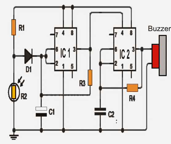
For executing the entire operation a couple of timers ICs 555 are connected as shown in Figure.
When the LDR is not introduced to light the voltage on pin 2 (trigger) of the first IC 555 stays higher and its output (pin 3) is rendered low. Due to this the second IC 555 is rendered inhibited (low voltage level on pin 4) and the alarm is not allowed to activate.
When the LDR experiences an illumination (door is opened), the voltage level on pin 2 of the first 555 gets low causing the output (pin 3) to oscillate (square wave).
During the oscillation when output of the first 555 is at high level enables the second 555 to get triggered which also begins oscillating in tune with the first but at a much higher frequency.
A buzzer which may be seen connected with the output of IC2 now begins buzzing and alarming.
The circuit makes use of a PP3 9 volt battery, and should be placed as close as possible to the inner light of the refrigerator.
The circuit should be housed inside a box that may be waterproof and sealed to prevent moisture from affecting its operation.
Circuit Diagram
Parts list of the refrigerator door open alarm circuit
- IC1 - IC2: 2 Timer 555
- C1: 1uf 25V
- C2: 100nF
- R1: 10K 1 / 4W
- R2: LDR (photoresistor)
- R3: 2.2M 1 / 4W
- R4: 1M 1 / 4W
- D1:1N4148
- Buzzer: Piezo type DC
Another Simpler Design
The above fridge door open warning circuit can be much simplified as shown in the following diagram:
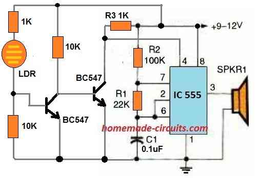
Here the IC 555 is configured as an astable frequency generator which creates an oscillating frequency on the connected speaker so that the speaker can emit a warning tone.
For the 555 astable to emit the sound it is necessary that pin#4 is connected to the positive line and is not grounded by the right side BC547 transistor.
However, when the fridge door is open, the internal lamp illuminates and the light falls on the LDR. The LDR resistance drops causing a voltage supply at the base of the left side BC547. This BC547 now conducts so that the base of the right side BC547 is grounded. Due to this the right side BC547 shut off.
This in turns allows the pin#4 of IC 555 to get a positive potential via R3 1K resistor.
IC 555 astable now becomes active and starts generating a warning tone on the speaker.
As soon as the fridge door is closed, the internal lamp shuts off causing a total darkness on the LDR. The LDR resistance increases drastically causing the left side BC547 to shut off.
Due to this right side BC547 switches ON and its collector grounds the pin#4 of the IC 555.
IC 555 now shuts down switching OFF the speaker warning tone.
The above concept can be further simplified as given in the following diagram:
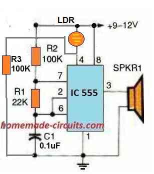
If the circuit does not work correctly try reducing the R3 value to 10K.
About first design how long will 9v battery be able to power circuit
Not sure about it, it will depend on how much current the IC555 consumes….to keep the consumption to minimum you can use the IC 7555 and replace R1 with 100k
Thanks
Hello everyone. Is there any hobbyist who tried this alarm who can tell me if the schematic is correct? Unfortunately I have built the circuit both physically and also simulated with tinkercad, but in both cases it doesn’t work. That is, even by varying the intensity of the light, the piezo does not emit any sound. I also tried the variant with the delay, but that doesn’t work either. I hope someone can help me. Thank you all
The above circuit was not designed by me so I am not very sure about its functioning.
You can try the following design which will work without fail.
However you will still need to tweak some of the parts a bit to get perfect results.
I hope you will first understand the working of the circuit before attempting it.
" rel="ugc">
Hi. Where should the power supply be placed in the diagram?
Positive to the top line which connects pin8 of the ICs, and negative to the lower line which connects with pin1 of the ICs.
Many thanks
Hello,
I understand that in the above circuit the alarm starts beeping when the fridge door is opened. What changes should be made, so the alarm starts beeping after a certain time after door of the fridge is open.
Thanks!
You can try the following concept. The R3 and C1 decides the delay time, which will be equal for both ON and OFF time of the buzzer, meaning the buzzer will keep sounding for sometime even after the fridge door is closed.
" rel="ugc">
I am a mom with 4 kids who don’t shut the fridge properly, which freezes up the fridge. Your directions look like greek to me. Do you make these for people to purchase? Instructions for circuit boards are the only thing I have found on line.
#NotAnEngineerJust(a)MOM
Thank you kris Morris! I am sorry I don’t sell readymade kits, however I can provide a much easier alternative with just a couple of parts, which you can buy and assemble yourself without going through any technical hassles, I’ll try to update the design soon in the above article…
Would this be sensitive enough to be triggered by the tiniest amount of light from outside the fridge if the door was ajar ?
yes it can be done by increasing the value of R1 appropriately.
Ok, thank you. Can you suggest anything to step up 6 v to 7 volt to use 2 led in series to save the energy and make circuit more efficient.
for stepping up the voltage you may have to employ a complex boost circuit, the easier option is to use single LEDs across the battery, all in parallel….by dropping the 6V to 3.5V through series diodes, or by using a emitter follower circuit as shown below:
https://www.homemade-circuits.com/2012/08/simplest-dc-cell-phone-charger-circuit.html
the 9V zener could be replaced with a 3.3V zener for dropping the voltage to the required limits
Hi Swagatam
Sometimes, the inner light of the refrigerator goes bad and most of the consumers don't replace them. In that case, the above circuit won't work.
I suggest, you can include in this article, another version of this circuit based on LM334, a thermistor or 1n4007 as temperature sensor. The sensor may be placed on the body of fridge just beneath the door. When the door is left opened, the cold air which is denser would escape from the lower part and come into contact with the sensor which will activate the buzzer after preset time. In this situation, it won't be required to place the circuit inside the fridge.
Hi Abu-Hafss,
It's hard to imaging how somebody could keep the fridge without a light, but even in that case the external light entering the fridge would be sufficient to trigger the LDR whenever the door is opened.
Another option is to use a hall effect sensor or a reed switch to sense the door's rubber seal magnet while it's closed or opened, and trigger the alarm.
Swagatam
I had thought about the external light but, at night it won't work.
However, hall-effect or reed switch would be better option.
I don't think at pitch dark the user himself would be able to see the fridge materials…there has to be some light to see things.
Suppose, the user opens his fridge (with inner light out of order) at night. He will use the room light for taking out the food. He closes the door and switches off the room light. But the door is not fully closed…………………………????
that's a 0.1% scenario, in such a terrible case this circuit won't help after all it's a straightforward, cheap and built on an extremely basic principle.
because if the door is open by 1 or 2 mm then even the internal lights would be off disabling the LDR….and in a case where the door is left sufficiently open and the user completely ignores the buzzer, walks of switching off the room light then it's his problem not the circuit's problem.
actually the circuit can be even more simplified by using just one IC….this circuit was not designed by me.
Actually, I misunderstood the circuit to warn when the door is not properly closed so that is not the circuits problem, it was my mistake
Ram, don't make it because it's not quite efficient, lot of power is wasted in the transformer. I have tested it
It's better to connect the LEDs directly with the battery through a calculated resistor.